introduction
Children and dogs can orient themselves and perform gymnastic maneuvers effortlessly. Some people think it's "child's play" until they try to mimic this ability in a robot. The human orientation system is incredibly complex, and it works very well when we are on the ground. In contrast, when we are in an aircraft, we are in an unfamiliar three-dimensional environment, and the lack of visual orientation references makes it difficult or impossible to manage spatial (distance) orientation. Between 5% and 10% of general aviation accidents are related to spatial disorientation, and 90% of these are fatal (Reference 1).
Microelectromechanical system (MEMS) inertial sensors are designed to be motion sensitive by nature and can effectively detect and process linear acceleration, magnetic heading, altitude, and angular rate information. To fully exploit the performance potential of inertial sensors, designers must be familiar with the overall mechanical system and pay close attention to the sources of motion and resonance in the application.
This article describes how MEMS inertial sensors (such as gyroscopes and accelerometers) can help people or machines overcome spatial orientation problems. The article describes the effects of external forces and motion on system operation, and the direct impact of component layout and mounting conditions (spatial relationships) on MEMS inertial sensor performance. System configurations vary (e.g., board size, material, mounting method), and designers need to design specific solutions based on specific applications. The article also describes how to detect and reduce erroneous inertial signals. For situations where harmful motion signals and system resonances occur in real-world environments, the article provides practical suggestions for enhancing sensor system operation.

Human balance
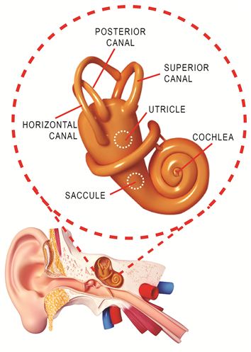
This article begins by discussing balance, using the human ear as an example. The cochlea in Figure 1 is the organ of hearing. The eardrum vibrates the cochlea through some of the smallest bones in our body. The cochlea has fine hairs, or cilia, and is filled with fluid. When the cochlea moves, the fluid does not move due to inertia. The cilia sense this difference in motion and transmit nerve impulses to our brain, which manifest as sound.

Figure 1. Balance and hearing in the human body are part of a complex balance organ in the inner ear.
The human ear also contains a motion detection system for balance. The three semicircular canals act like mutually perpendicular gyroscopes, sensing and sending impulses to the brain that indicate a person's state of balance. Unfortunately, there are limitations to the way we sense motion.
We cannot sense motion if it is less than 2 degrees per second, and we stop sensing motion if it is steady for more than 20 to 25 seconds. This human limitation can cause confusion. There are two other sensory organs in the inner ear: the utricle senses linear acceleration, and the saccule senses gravity. All five sensory organs in the ear send information about the body's position and movement to the brain, helping us balance. Together with the eyes, this helps us maintain balance and keep our eyes on a target when the head moves or the body rotates.
Pilots and spatial orientation in airplanes
Pilots know not to fly by instinct (i.e. not relying on inner senses) but by relying on flight instruments. This is very difficult to master, especially in emergency and panic situations.
According to the Federal Aviation Administration (FAA), pilots are subject to a common illusion called the "graveyard hover." This is related to returning to level flight after a long, conscious or unconscious, banked turn. For example, when a pilot begins a banked turn to the left, he or she will initially feel a turn in the same direction; if the turn continues to the left (for about 20 seconds or more), the pilot will feel that the aircraft is no longer turning left. At this point, if the pilot attempts to level the wings, this action will cause the pilot to feel that the aircraft is turning and banking in the opposite direction (to the right). If the pilot believes the illusion of turning to the right (which can be very strong), he or she will attempt to correct the feeling of turning right and thus re-enter the initial left turn. Unfortunately, while this is happening, the aircraft is still turning left and descending. Pulling up on the control stick and adding power while the turn is in progress is not a good idea - it will only turn the aircraft further to the left. If the pilot does not recognize the illusion and fails to level the wings, the aircraft will continue to turn left and lose altitude until it impacts the ground (Reference 2).
The question is, can MEMS gyroscopes and accelerometers help pilots overcome spatial disorientation?
MEMS inertial sensors are the solution
The human body can be deceived and must rely on external help in some cases to achieve good balance. Since the human body is susceptible to spatial disorientation, MEMS inertial sensors offer a solution. Properly installed inertial sensors can be used to establish an inertial coordinate frame reference that can be used to help determine direction and/or motion. Using these devices, the hidden dangers of false perception can be avoided.
To ensure reliable operation of inertial sensors, they must be properly mounted and oriented. There is a set of good design practices for assembling inertial sensors that, when applied properly, can result in a high-performance system.
A Practical Approach to Assembling MEMS Inertial Sensors
It is important to understand the basics from the beginning: the location of the inertial sensor on the PCB is likely to be the first thing to consider when vibration occurs. Therefore, how the inertial sensor is mounted, the mounting conditions, and its placement/orientation will affect the overall mechanical system characteristics. In short, if the design is not carefully considered, the inertial signal performance will degrade when motion occurs.
NOTE: It is also highly recommended to analyze the total mechanical system and its impact on the inertial sensor performance.
Arrangement matters
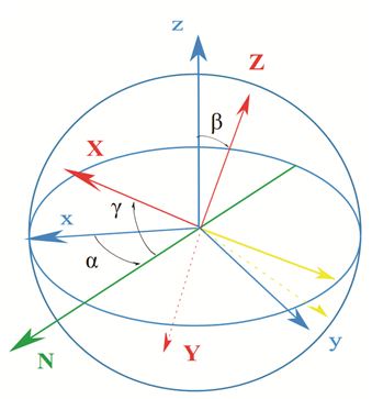
Let’s start with orientation. Placing an inertial sensor relative to a reference (often a selected PCB side) and maintaining that orientation during the assembly reflow process is challenging. Additionally, each level of assembly (sensor to package, package to PCB, PCB to housing, etc.) adds installation errors. Since the orientation of the sensor assembly (relative to the inertial coordinate system) determines the accuracy of the system, all errors must be minimized at this point. Figure 2 shows the errors caused by incorrect orientation. Software can calibrate assembly errors, but higher-order errors can degrade sensor performance if the error sources are not limited.

Figure 2. Illustration of inertial sensor assembly error. Image source: Juansempere, en.wikipedia
Thermomechanical stress is a potential source of error that can create thermal gradients on the inertial sensor, causing package stress, and thermal gradients on the PCB, transferring stress to the inertial sensor. These two thermal effects are sometimes difficult to distinguish, and in some cases both are present. The resulting package stress can cause deviation (and offset) and sensitivity performance errors. Devices that generate more heat should be kept away from the inertial sensor, but this requirement is sometimes difficult to meet in practical compact PCB designs. In any case, every effort must be made to keep the inertial sensor away from heat sources to minimize temperature gradients.
Assembly matters
Component placement requires understanding and applying the optimal temperature for a particular reflow. Because these operations are often focused on solder joint strength, reliability, and yield (i.e., cost), special considerations for inertial sensors are sometimes overlooked. For example, a non-optimized cooling phase can create residual stresses in the inertial sensor package, which can degrade performance, causing deviations and scaling factors beyond specifications.
Conformal coating of PCBs is often used to protect circuits from moisture, chemical contamination (e.g., salt), and other damaging influences. Conformal coating is not recommended for inertial sensor devices. The coating changes the mechanical condition of the sensor, affecting the overall mechanical system characteristics. It is also difficult to control the application of conformal coatings (i.e., viscosity, dry thickness).
Mechanical system matters
External sources of motion (e.g., inertial signals, shock, vibration) can accidentally excite the PCB to resonate, and under worst-case operating conditions, it can happen that the inertial signals are actually artifacts caused by system resonances. These erroneous signals act as noise, masking the inertial signals (e.g., movement and/or vibration). When resonant conditions occur, the position of the inertial sensor relative to the valleys, nodes, and peaks on the PCB can cause signal detection performance to degrade.
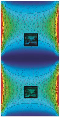
Figure 3 shows two ways to place the inertial sensor on a PCB, with the main resonant modes marked. The sensor in the lower left position is located in the node region (cyan). The angular rate associated with the resonance is reduced in this location relative to the sensor in the upper right of the PCB. The second inertial sensor is located at the edge between the node region and the slope of the trough (shown in dark blue). This sensor is in an unbalanced position and is more susceptible to distortion of the acceleration and angular rate signals under resonant conditions.

Figure 3. Simulation of PCB resonance and inertial sensor placement. The resonance-related angular rate signal at the sensor location in the lower section is attenuated. The second sensor at the top is in an unbalanced position and is more susceptible to acceleration and angular rate signal distortion. PCB images courtesy of FEKO, copyright reserved.
Previous article:Choosing the best multi-core architecture for compute-intensive applications
Next article:CSR Bluetooth Networking Smart Home Solution
Recommended ReadingLatest update time:2024-11-23 16:42


- "Cross-chip" quantum entanglement helps build more powerful quantum computing capabilities
- Why is the vehicle operating system (Vehicle OS) becoming more and more important?
- Car Sensors - A detailed explanation of LiDAR
- Simple differences between automotive (ultrasonic, millimeter wave, laser) radars
- Comprehensive knowledge about automobile circuits
- Introduction of domestic automotive-grade bipolar latch Hall chip CHA44X
- Infineon Technologies and Magneti Marelli to Drive Regional Control Unit Innovation with AURIX™ TC4x MCU Family
- Power of E-band millimeter-wave radar
- Hardware design of power supply system for automobile controller
 Professor at Beihang University, dedicated to promoting microcontrollers and embedded systems for over 20 years.
- Intel promotes AI with multi-dimensional efforts in technology, application, and ecology
- ChinaJoy Qualcomm Snapdragon Theme Pavilion takes you to experience the new changes in digital entertainment in the 5G era
- Infineon's latest generation IGBT technology platform enables precise control of speed and position
- Two test methods for LED lighting life
- Don't Let Lightning Induced Surges Scare You
- Application of brushless motor controller ML4425/4426
- Easy identification of LED power supply quality
- World's first integrated photovoltaic solar system completed in Israel
- Sliding window mean filter for avr microcontroller AD conversion
- What does call mean in the detailed explanation of ABB robot programming instructions?
- STMicroelectronics discloses its 2027-2028 financial model and path to achieve its 2030 goals
- 2024 China Automotive Charging and Battery Swapping Ecosystem Conference held in Taiyuan
- State-owned enterprises team up to invest in solid-state battery giant
- The evolution of electronic and electrical architecture is accelerating
- The first! National Automotive Chip Quality Inspection Center established
- BYD releases self-developed automotive chip using 4nm process, with a running score of up to 1.15 million
- GEODNET launches GEO-PULSE, a car GPS navigation device
- Should Chinese car companies develop their own high-computing chips?
- Infineon and Siemens combine embedded automotive software platform with microcontrollers to provide the necessary functions for next-generation SDVs
- Continental launches invisible biometric sensor display to monitor passengers' vital signs
- Bluetooth Technology Principle and Test
- EEWORLD University Hall ---- Intelligent Instrument Jilin University
- Inductors and Inductors
- MT7921 solution WIFI6 wireless network card driver compilation method
- How to choose external memory for DSP?
- How to quickly and securely connect IoT applications to Google Cloud
- Research on control scheme of dynamic voltage restorer based on flexible phase-locked loop
- What is an Operational Amplifier?
- Development and Application of Active Power Filter
- Summary of key points of the exam "Analog Circuits and Digital Circuits"


 Sensor Principles and Applications (Yan Xin)


 京公网安备 11010802033920号