CS1240 is a precision analog-to-digital conversion (ADC) chip developed in China with a resolution of 24 bits and an effective accuracy of up to 21 bits. It can be widely used in industrial process control, electronic scales, gas/liquid detectors, blood meters, etc. kind of application. This article describes the main features of the chip and discusses the typical application circuit of CS1240 using ordinary and high-precision electronic scales as examples.
Typical application circuit
 ?
?
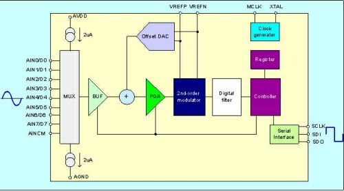
Figure 1: CS1240 chip functional structure diagram
The CS1240 independently developed by Chipsea Technology Co., Ltd. is a 24-bit high-precision, low-power consumption Σ-Δ analog-to-digital conversion chip. It has a resolution of 24 bits and an effective accuracy of up to 21 bits. It can operate at a power supply voltage of 2.7V-5.5V. working conditions.
CS1240 has 8 analog input terminals and 8 digital input and output channels. You can choose the input channel analog buffer or directly input the signal to the analog-to-digital converter. The analog buffer can effectively improve the input impedance of the chip. The chip provides internal test current (2 microamps) to detect open or short circuit conditions at the input. The integrated 8-bit analog-to-analog converter (DAC) can adjust the bias voltage of the input signal through register control, effectively expanding the range of the input signal, and can adjust up to 50% of the full range (FS).
CS1240/1241 has an on-chip programmable gain amplifier (PGA) of 1 to 128 times. At 128 times, the effective resolution can reach 19 bits. The modulator is a second-order Σ-Δ modulator, and the chip's FIR filter provides 50Hz and 60Hz notch filtering, which effectively improves the chip's anti-interference performance.
CS1240/1241 provides a serial interface bus that is compatible with the serial peripheral interface (SPI) and can be configured to use up to 8 digital I/Os. It only requires a small number of peripheral components to form a variety of application circuits. The functional structure diagram of CS1240 is shown in Figure 1.

Figure 2: Basic components of an electronic scale system
Electronic scales are currently commonly used measuring instruments and are widely used in people's daily lives. Figure 2 shows the basic schematic diagram of an electronic scale.
Due to the rich functions of CS1240 and the SPI interface that can easily communicate with the MCU, only a very small number of peripheral components can be used to form a variety of application solutions, which is especially suitable for use in electronic scales. For example, since the PGA is built-in, there is no need for external amplification circuits, which can reduce system noise and cost. The chip is equipped with a self-correction circuit and a system correction circuit, which can correct the gain error and offset error of the chip and the system, further improving the accuracy. The reference voltage input of CS1240 can directly use the power supply voltage, so that no additional reference source is needed, which can simplify circuit design and reduce costs.
1. Ordinary electronic scale design plan
Figure 3 is a schematic diagram of an ordinary electronic scale circuit implemented using CS1240. The signal from the sensor is filtered by an external passive filter and then sent to the CS1240. The filter consists of two parts: the first part is an EMI filter composed of inductors and capacitors, used to reduce the impact of the external environment on the circuit; the second part is an RC filter composed of resistors and capacitors, used to limit the input signal bandwidth to reduce the noise of the input signal.
Since CS1240 has its own PGA circuit inside, the amplification part shown in Figure 2 is not needed in this circuit. The gain of the PGA is generally set to 64 or 128. The reference voltage input can be connected directly to power and ground, so no additional reference voltage is required. In order to reduce the noise of the reference source, a 10uF filter capacitor needs to be added to the input end of the reference source. The closer this capacitor is to the chip, the better. Before the circuit works normally, the gain error and offset error of the chip and system can be corrected through self-correction and system correction to improve the accuracy of the entire system.

Figure 3: Electrical schematic diagram of ordinary electronic scale circuit
CS1240 communicates with the MCU through the SPI interface. The SPI interface is a standard four-wire SPI interface, including chip select signal CS, serial clock SCLK, serial input SDI and serial output SDO. Through the SPI interface, each control register and data register in the CS1240 can be read and written. It can be seen that the entire circuit only requires a very small number of peripheral components (mainly some passive components such as capacitors, inductors, and resistors that play a filtering role), and is very simple to implement.
What needs to be noted when designing the circuit is that because the CS1240 is a digital-analog mixed chip, in order to prevent the noise of the digital part from affecting the analog circuit, it is best to use separate digital power supplies and analog power supplies, and add a bypass capacitor to the input end of the capacitor. To reduce the impact of power supply noise on the circuit. When making a PCB board, the digital ground and analog ground should be separated and finally connected through a single point of contact.
2. High-precision electronic scale design scheme
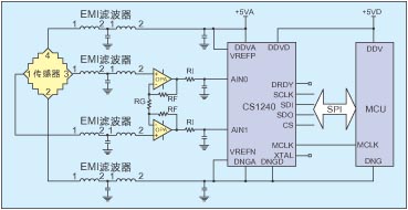
Generally speaking, the voltage value output by the sensor is very small, basically in the millivolt level or even microvolt level. When designing a high-precision electronic scale, an external amplification circuit is required to obtain sufficient gain. Figure 4 shows the circuit schematic diagram of a high-precision electronic scale.
Compared with the solution shown in Figure 3, this circuit mainly adds an amplification circuit composed of two operational amplifiers (op amps for short) and resistors RG and RF. The gain of this amplifier circuit is:

Figure 4: Electrical schematic diagram of high-precision electronic scale
By adjusting the values of RG and RF, the required gain can be obtained. With the maximum 128 times gain provided by CS1240, the input signal can be amplified to the required amplitude.
When selecting an op amp, please note that since the amplitude of the input signal is very small, the noise performance and offset voltage of the op amp are very high. You should choose an op amp with low noise and low offset.
Summary of this article
At present, electronic scales are developing in the direction of miniaturization, high precision, and intelligence. CS1240 adopts SSOP28-pin package with an outline of 10.2×5.3mm. It is very small and requires few peripheral devices, which meets the needs of miniaturization of electronic scales. It also provides 24-bit no missing code and 21-bit effective accuracy. The high performance meets the high-precision requirements of electronic scales; it has built-in various control registers and data registers, and these registers can be easily controlled and read through the SPI interface, meeting the needs of intelligent electronic scales. Therefore CS1240 is an ideal choice for analog-to-digital converters in electronic scales.
Previous article:Application of 24-bit Σ-Δ analog-to-digital converter CS1240 in electronic scales
Next article:Selection of high-speed A/D converters
Recommended ReadingLatest update time:2024-11-16 19:56


- Popular Resources
- Popular amplifiers
- High signal-to-noise ratio MEMS microphone drives artificial intelligence interaction
- Advantages of using a differential-to-single-ended RF amplifier in a transmit signal chain design
- ON Semiconductor CEO Appears at Munich Electronica Show and Launches Treo Platform
- ON Semiconductor Launches Industry-Leading Analog and Mixed-Signal Platform
- Analog Devices ADAQ7767-1 μModule DAQ Solution for Rapid Development of Precision Data Acquisition Systems Now Available at Mouser
- Domestic high-precision, high-speed ADC chips are on the rise
- Microcontrollers that combine Hi-Fi, intelligence and USB multi-channel features – ushering in a new era of digital audio
- Using capacitive PGA, Naxin Micro launches high-precision multi-channel 24/16-bit Δ-Σ ADC
- Fully Differential Amplifier Provides High Voltage, Low Noise Signals for Precision Data Acquisition Signal Chain
- Innolux's intelligent steer-by-wire solution makes cars smarter and safer
- 8051 MCU - Parity Check
- How to efficiently balance the sensitivity of tactile sensing interfaces
- What should I do if the servo motor shakes? What causes the servo motor to shake quickly?
- 【Brushless Motor】Analysis of three-phase BLDC motor and sharing of two popular development boards
- Midea Industrial Technology's subsidiaries Clou Electronics and Hekang New Energy jointly appeared at the Munich Battery Energy Storage Exhibition and Solar Energy Exhibition
- Guoxin Sichen | Application of ferroelectric memory PB85RS2MC in power battery management, with a capacity of 2M
- Analysis of common faults of frequency converter
- In a head-on competition with Qualcomm, what kind of cockpit products has Intel come up with?
- Dalian Rongke's all-vanadium liquid flow battery energy storage equipment industrialization project has entered the sprint stage before production
- Allegro MicroSystems Introduces Advanced Magnetic and Inductive Position Sensing Solutions at Electronica 2024
- Car key in the left hand, liveness detection radar in the right hand, UWB is imperative for cars!
- After a decade of rapid development, domestic CIS has entered the market
- Aegis Dagger Battery + Thor EM-i Super Hybrid, Geely New Energy has thrown out two "king bombs"
- A brief discussion on functional safety - fault, error, and failure
- In the smart car 2.0 cycle, these core industry chains are facing major opportunities!
- The United States and Japan are developing new batteries. CATL faces challenges? How should China's new energy battery industry respond?
- Murata launches high-precision 6-axis inertial sensor for automobiles
- Ford patents pre-charge alarm to help save costs and respond to emergencies
- New real-time microcontroller system from Texas Instruments enables smarter processing in automotive and industrial applications
- How does FPGA adjust the volume of the buzzer?
- [Repair] Repaired a data cable
- How long will the battle between community owners and communication base stations last?
- Please tell me the winding method and other parameters of the EE8 transformer that can increase 0.7V to 7V
- Conversion between CC2640R2F projects
- Pengfeng Technology RVBoards-Nezha (RISC-V SBC) Allwinner Development Board Introduction Part 3
- Cadence Certus Closure Solution is a new generation chip-level convergence solution. Welcome to learn more!
- What is the progress of domestic NPU chips?
- How is JTAG used for chip testing?
- Talk about downloading the DSP28335 register manual

 Modern Electronic Technology Training Course (Edited by Yao Youfeng)
 【Follow me Season 2 Episode 1】-Mission Code (Adafruit Circuit Playground Express Development Board)
 【Follow me Season 2 Episode 1】Source code


 京公网安备 11010802033920号