Abstract: This paper introduces a miniaturized and rugged universal automotive pressure sensor suitable for mass production, which is designed by combining silicon piezoresistive elements manufactured by MEMS (micro electro mechanical systems) technology with intelligent integrated signal conditioning technology. The zero and full scale of the sensor are temperature calibrated by intelligent conditioning technology to achieve high-precision measurement in a wide temperature working range, and is suitable for mass production.
0 Introduction
The continuous improvement of today's automobile performance is due to the continuous development of automotive electronics. Among them, the representative core component is the sensor. The sensor converts various physical signals into electrical signals and transmits the specific state of the car to the electronic control unit to realize the car control. As a key component of automotive electronics, it has attracted much attention in today's booming electronic technology. Fleming, an American automotive sensor authority, pointed out the bright prospects of MEMS technology in the field of automotive sensors in his review of automotive electronics technology in 2000. A diffused silicon pressure sensor based on MEMS technology and intelligent signal conditioning was designed to cope with the pressure detection of the automotive pressure system.
1 Sensor Principle and Packaging Design
In order to convert the pressure signal into an electrical signal, the strain principle is adopted, and the Wheatstone detection bridge is made on a single crystal silicon wafer through MEMS technology. This makes the single crystal silicon wafer a sensitive element integrating stress sensitivity and force-electric conversion, as shown in Figure 1.
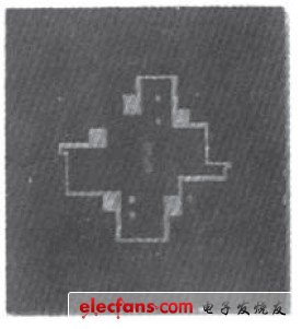
Figure 1 Sensitive element
When the silicon chip is subjected to external stress, the resistance of the bridge arm of the silicon strain bridge will change, generally in the Wheatstone bridge detection mode, as shown in Figure 2.

Figure 2 Wheatstone bridge
Its output voltage is expressed as vo=KAR/R (Rl=R3=R4, △R1=△R3=△R2=△R4).
Since the change in resistance is directly related to the stress P, then:
![]()
Where: Vo is the output voltage, mV; S is the sensitivity, mV/V/Pa; P is the external force or stress, Pa; VB is the bridge voltage, and VOS is the zero position output, mV.
A single silicon chip can only be used as part of a detection unit and cannot independently complete signal conversion, so it must be packaged specifically to enable it to have the ability to detect pressure. The silicon chip in Figure 2 is electrostatically sealed with a PYREX glass ring.
The PYREX glass ring serves as a mechanical support for the silicon chip to support the elastic sensitive element and insulate the silicon chip from the package, while the hole in the PYREX glass ring becomes the reference pressure cavity and electrode lead cavity of the sensor. Its structure is shown in Figure 3.
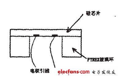
Figure 3 Sensitive component packaging
After the sensitive core as shown in FIG3 is sealed on the metal threaded base to form a pressure-inlet cavity, it becomes an installable pressure measurement front end, as shown in FIG4 .

Figure 4 Installable pressure measurement front end
This packaging technology can withstand a pressure of at least 15 MPa, and can withstand a pressure of 100 MPa if specially processed.
2. Intelligent adjustment design of sensor multiples
As shown in Figure 2, the sensor output voltage signal Vo=VB△R/R (R1=R2=R3=R4, △R1=△R2=△R3=△R4), in an ideal state, its signal output is a linear change value. However, the sensor made of single crystal silicon is a semiconductor sensor and is greatly affected by temperature. This causes the output of the sensor to change when the ambient temperature changes, affecting the reading accuracy. Adding the effect of temperature on the bridge in Figure 2 yields the following formula:

but

Ideally, if:

However, the influence of temperature is great in the automotive application environment, so compensation technology must be used. Figure 5 is a set of measured temperature-pressure curves of a wide temperature range of an uncompensated sensor. Obviously, in the commonly used operating temperature range of the car, the readout error introduced by temperature reaches about 10%, which is obviously not allowed. The traditional compensation method is to compensate by connecting resistors in series and parallel on the bridge arm. In order to improve the working efficiency, the method of laser trimming the thick film resistor network pre-made on the ceramic substrate is used to achieve this. However, this method has many disadvantages and limitations, and the accuracy after compensation in a wide temperature range is only 2% to 3%, which does not meet the requirements of automotive pressure measurement.
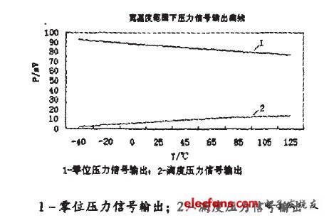
Figure 5 Pressure signal output curve under wide temperature range
The latest sensor signal conditioning technology is to convert the weak signal of the sensor into a standard voltage signal by using digital signal processing, and then implant a model algorithm to compensate the output standard signal to a certain accuracy range.
The signal processing link block diagram is shown in Figure 6.
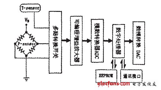
Figure 6 Signal processing link block diagram
With the assistance of the temperature sensor, the signal conversion switch reads the pressure and temperature values in time, amplifies the weak signal through the programmable gain amplifier, and then enters the digital processor to calculate the compensated pressure under the current temperature and pressure through the ADC quantization sensor signal, and outputs the analog signal to the digital-to-analog converter DAC. The temperature compensation parameters can be written into the EEPROM through the communication interface for the digital processor to call when calculating. So many functional components can be integrated on a single chip, making it easy to encapsulate the ASIC circuit and the pressure sensitive chip made by MEMS technology in a small housing.
The sensor after actual measurement and calibration in a wide temperature range effectively suppresses the influence of temperature changes on it. As shown in Figure 7, the wide temperature calibration data curve of multiple sensors with standard signal output: It is not difficult to see that the read temperature error of the sensor calibrated by this method in a wide temperature working environment is about 1%-2% FS, which meets the high-precision measurement requirements of a wide temperature, and the calibration method through a multi-channel communication interface is compatible with batch manufacturing technology, achieving the high cost-effectiveness requirements of manufacturing automotive sensors.
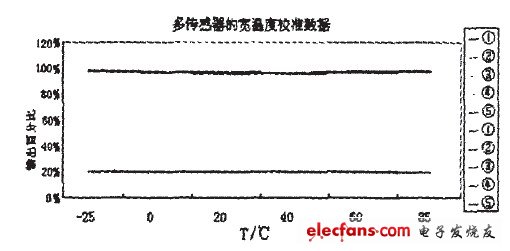
Figure 7 Multi-sensor wide temperature calibration data curve
3 Comprehensive package and conclusion
The sensor and signal conditioning circuit board are packaged in a stainless steel metal housing with a diameter of 23mm and a height of 27.5mm, and a connector is used at one end of the sensor as a signal connection to facilitate testing and maintenance. The overall packaging is shown in Figure 8.

Figure 8 Overall package appearance
The MEMS silicon piezoresistive automotive pressure sensor has become a practical product with high cost performance through the combination of MEMS technology, packaging technology and information technology. It is a combination of contemporary advanced technologies and its development deserves attention.
Previous article:Design of an Embedded Network Interface
Next article:Capacitive Sensing in Human Contact Applications
Recommended ReadingLatest update time:2024-11-15 15:51


- High signal-to-noise ratio MEMS microphone drives artificial intelligence interaction
- Advantages of using a differential-to-single-ended RF amplifier in a transmit signal chain design
- ON Semiconductor CEO Appears at Munich Electronica Show and Launches Treo Platform
- ON Semiconductor Launches Industry-Leading Analog and Mixed-Signal Platform
- Analog Devices ADAQ7767-1 μModule DAQ Solution for Rapid Development of Precision Data Acquisition Systems Now Available at Mouser
- Domestic high-precision, high-speed ADC chips are on the rise
- Microcontrollers that combine Hi-Fi, intelligence and USB multi-channel features – ushering in a new era of digital audio
- Using capacitive PGA, Naxin Micro launches high-precision multi-channel 24/16-bit Δ-Σ ADC
- Fully Differential Amplifier Provides High Voltage, Low Noise Signals for Precision Data Acquisition Signal Chain
- LED chemical incompatibility test to see which chemicals LEDs can be used with
- Application of ARM9 hardware coprocessor on WinCE embedded motherboard
- What are the key points for selecting rotor flowmeter?
- LM317 high power charger circuit
- A brief analysis of Embest's application and development of embedded medical devices
- Single-phase RC protection circuit
- stm32 PVD programmable voltage monitor
- Introduction and measurement of edge trigger and level trigger of 51 single chip microcomputer
- Improved design of Linux system software shell protection technology
- What to do if the ABB robot protection device stops
- Huawei's Strategic Department Director Gai Gang: The cumulative installed base of open source Euler operating system exceeds 10 million sets
- Download from the Internet--ARM Getting Started Notes
- Learn ARM development(22)
- Learn ARM development(21)
- Learn ARM development(20)
- Learn ARM development(19)
- Learn ARM development(14)
- Learn ARM development(15)
- Analysis of the application of several common contact parts in high-voltage connectors of new energy vehicles
- Wiring harness durability test and contact voltage drop test method
- 【Zero Knowledge ESP8266】Tutorial: OLED Weather Clock
- EEWORLD University Hall----Introduction to Isolation Amplifier
- [RVB2601 Creative Application Development] CDK startup does not respond
- How to use the serial port of Sinlinx A33 development board
- Several issues about gate drivers
- In-depth analysis | RF front-end technology in the 5G era
- XILINX FPGA Chip
- Studying the road to electric motor drive - 7: Mathematics used in electric motor drive
- Design of a Frequency Shift Keying Wireless Modem
- FAQ: How to design an efficient and reliable USB PD power supply in minutes - PI Expert step-by-step tutorial

 Sensor Principles and Applications (Yan Xin)


 京公网安备 11010802033920号