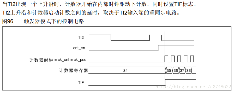
In this article, the trigger mode is used instead of the gate mode.
code show as below:
void TIM3_PWMShiftInit(void)
{
TIM_TimeBaseInitTypeDef TIM_TimeBaseInitStruct;
GPIO_InitTypeDef GPIO_InitStruct;
TIM_OCInitTypeDef TIM_OCInitStruct;
/**********************TIM3 GPIO configuration****************************/
RCC_APB2PeriphClockCmd(RCC_APB2Periph_GPIOB|RCC_APB2Periph_GPIOA, ENABLE);
GPIO_InitStruct.GPIO_Mode = GPIO_Mode_AF_PP;
GPIO_InitStruct.GPIO_Pin = GPIO_Pin_0|GPIO_Pin_1|GPIO_Pin_13;
GPIO_InitStruct.GPIO_Speed = GPIO_Speed_50MHz;
GPIO_Init(GPIOB,&GPIO_InitStruct);
GPIO_InitStruct.GPIO_Pin = GPIO_Pin_8;
GPIO_Init(GPIOA,&GPIO_InitStruct);
/**********************Initialize TimBase structure****************************/
RCC_APB1PeriphClockCmd(RCC_APB1Periph_TIM3,ENABLE); //Turn on TIM clock
RCC_APB2PeriphClockCmd(RCC_APB2Periph_TIM1,ENABLE);
TIM_TimeBaseInitStruct.TIM_ClockDivision = TIM_CKD_DIV1; //Timer does not divide frequency
TIM_TimeBaseInitStruct.TIM_CounterMode = TIM_CounterMode_Up;
TIM_TimeBaseInitStruct.TIM_Period = 1799; //Frequency = 72000000/PSC/(ARR+1) = 40KHz
TIM_TimeBaseInitStruct.TIM_Prescaler = 0;
TIM_TimeBaseInit(TIM3, &TIM_TimeBaseInitStruct);
TIM_TimeBaseInit(TIM1, &TIM_TimeBaseInitStruct);
/**********************Initialize TIM3 OC structure****************************/
TIM_OCInitStruct.TIM_OCMode = TIM_OCMode_PWM2;
TIM_OCInitStruct.TIM_OCPolarity = TIM_OCPolarity_Low;
TIM_OCInitStruct.TIM_OutputState = TIM_OutputState_Enable;
TIM_OCInitStruct.TIM_Pulse = 600; //TIM3 CH3 duty cycle: 600/(ARR+1)=33.3%
TIM_OC3Init(TIM3,&TIM_OCInitStruct);
//TIM1 CH1pwm output configuration
TIM_OCInitStruct.TIM_OCMode = TIM_OCMode_PWM2;
TIM_OCInitStruct.TIM_Pulse=600; //TIM1 CH1 duty cycle: 600/(ARR+1)=33.3%
TIM_OCInitStruct.TIM_OCPolarity=TIM_OCPolarity_Low; //Set output polarity
TIM_OCInitStruct.TIM_OutputNState=TIM_OutputNState_Disable; //Disable complementary terminal output. Output polarity cannot be adjusted without this statement.
TIM_OC1Init(TIM1,&TIM_OCInitStruct);
/**************************Configure phase shift trigger**************************/
TIM_OCInitStruct.TIM_OCMode = TIM_OCMode_PWM2; //PWM2 and Toggle modes can trigger phase shift, other modes cannot
TIM_OCInitStruct.TIM_Pulse = 600-2; //It takes about 2 timer cycles to trigger, phase shift: 360*600/(ARR+2)= 120 degrees
TIM_OC2Init(TIM1,&TIM_OCInitStruct); //Need CH2 rising edge trigger. If the phase shift cannot be triggered, please change the output polarity of CH2.
/**************************Configure master-slave mode****************************/
TIM_SelectOutputTrigger(TIM1, TIM_TRGOSource_OC2Ref); //TIM1 OC2 triggers slave timer
TIM_SelectMasterSlaveMode(TIM1, TIM_MasterSlaveMode_Enable);
TIM_SelectInputTrigger(TIM3, TIM_TS_ITR0); //ITRO trigger
TIM_SelectSlaveMode(TIM3, TIM_SlaveMode_Trigger);
TIM_Cmd(TIM1, ENABLE);
TIM_CtrlPWMOutputs(TIM1, ENABLE); //Advanced timer pwm output enable, be sure to turn it on

The oscilloscope displays the following waveform:
CH1: TIM1 CH1
CH2: TIM3 CH3


Figure 1 shows that the frequency and duty cycle are correct, and combined with Figure 2, it can be seen that the phase shift degree is correct.
After observing the output of the two timers at different frequencies and duty cycles, it was found that the phase shift had an error of about 25ns, so two timer cycle corrections were performed during initialization.
The oscilloscope is zoomed in to 25ns, and it can be seen that after correction by 600-2,2 timer cycles (the timer does not divide the frequency), the phase shift has basically no offset.
Previous article:STM32 advanced timer slave mode four
Next article:STM32 timer generates PWM--breathing light
- Popular Resources
- Popular amplifiers
- Learn ARM development(16)
- Learn ARM development(17)
- Learn ARM development(18)
- Embedded system debugging simulation tool
- A small question that has been bothering me recently has finally been solved~~
- Learn ARM development (1)
- Learn ARM development (2)
- Learn ARM development (4)
- Learn ARM development (6)
 Professor at Beihang University, dedicated to promoting microcontrollers and embedded systems for over 20 years.
- LED chemical incompatibility test to see which chemicals LEDs can be used with
- Application of ARM9 hardware coprocessor on WinCE embedded motherboard
- What are the key points for selecting rotor flowmeter?
- LM317 high power charger circuit
- A brief analysis of Embest's application and development of embedded medical devices
- Single-phase RC protection circuit
- stm32 PVD programmable voltage monitor
- Introduction and measurement of edge trigger and level trigger of 51 single chip microcomputer
- Improved design of Linux system software shell protection technology
- What to do if the ABB robot protection device stops
- CGD and Qorvo to jointly revolutionize motor control solutions
- CGD and Qorvo to jointly revolutionize motor control solutions
- Keysight Technologies FieldFox handheld analyzer with VDI spread spectrum module to achieve millimeter wave analysis function
- Infineon's PASCO2V15 XENSIV PAS CO2 5V Sensor Now Available at Mouser for Accurate CO2 Level Measurement
- Advanced gameplay, Harting takes your PCB board connection to a new level!
- Advanced gameplay, Harting takes your PCB board connection to a new level!
- A new chapter in Great Wall Motors R&D: solid-state battery technology leads the future
- Naxin Micro provides full-scenario GaN driver IC solutions
- Interpreting Huawei’s new solid-state battery patent, will it challenge CATL in 2030?
- Are pure electric/plug-in hybrid vehicles going crazy? A Chinese company has launched the world's first -40℃ dischargeable hybrid battery that is not afraid of cold
- Experience in Application Test of DSP External SRAM
- ADS amplifierMRF8P9040N verification simulation
- [National Technology N32 MCU Development Package] --N32L43x Series
- Power Amplifier
- The most detailed summary of embedded system knowledge and interface technology ever!
- Award-winning live broadcast | Rochester Electronics explains in detail: Challenges and solutions after semiconductor production shutdown
- Problems with current sinking and current sourcing of the I/O port of the msp430 microcontroller
- Newbie help, how to modify the contents of a file with the suffix bin
- From fail to pass, what does DDR debugging go through?
- Understand 20 types of analog circuits in one article


 LM2904PWLE


 京公网安备 11010802033920号