The purpose and main research content of the project
Research purposes
In order to remotely manage equipment and monitor the environment on site, simplify on-site monitoring equipment, and effectively improve the stability and security of the entire system, a remote controller is planned to be developed, referred to as RCM remote controller. The remote controller will integrate multiple functions such as on-site data collection, multiple communication protocol conversion, fault alarm, emergency control, intelligent linkage, and embedded WEB configuration page.
Main research content
1. Remote monitoring system
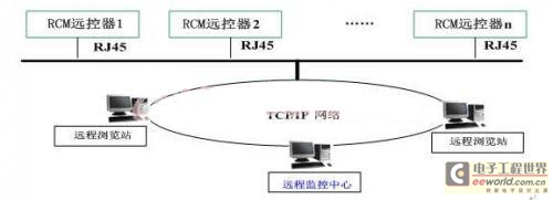
The overall structure of the remote monitoring system is shown in Figure 1, in which the main research content is the RCM remote controller.

figure 1
The remote controller is connected to the TCP/IP network open network through RJ45; the remote browsing station browses and obtains information through the IP address and password of the remote controller; the remote monitoring center implements real-time monitoring of the remote controller through the network. Here, the remote controller is a microcomputer system with data acquisition, data transmission and intelligent processing.
2. RCM remote control
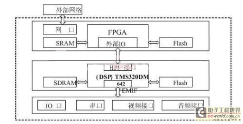
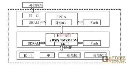
The interface type of the remote controller in the remote monitoring system is shown in Figure 2, and the internal block diagram is shown in Figure 3. It is mainly divided into two parts: hardware and software: the hardware design includes information acquisition module, DSP information processing module and FPGA processor module; the software design mainly includes DSP subsystem software design and FPGA subsystem software design.

Figure 2 Remote control interface type

Figure 3: Overall structure diagram of the remote controller
Interface Description:
Data Class
1) AI: 16 analog/digital conversion voltage input (0-5V DC or 0-20mA);
2) AO: 16 analog outputs;
3) DI: 32-channel optical isolation switch status input (TTL level) (4X8);
4) DO: 16-channel photo-isolation relay control output, 16-channel analog channel can realize one-to-one linkage;
5) RS232 serial port: 2; RS485 serial port: 4
6) RJ45: 2 10/100Base-T Ethernet ports (physical interface: RJ-45 socket); connection port: socket; protocol transmission: RTP/IP, UDP/IP, TCP/IP, or multicast IP.
7)POWER IN/OUT is the power input and output.
Video
VIDEO IN: 4 video inputs for image transmission, 1Vpp - 75 ohm; connector: BNC female.
Compression method: MPEG4; Transmission frame rate: 1-25 frames per second (PAL, adjustable, full real-time; Resolution: 176×144 to 720×576 (PAL); 176×120 to 704×480 (NTSC); Bandwidth: 30Kbit/sec. to 4Mbit/sec. adjustable; Image standard: NTSC or PAL; Image quality: adjustable.
Audio
AUDIO IN: 4-way audio input, -46 to -3dBV--1K ohm;
AUDIO OUT: 4 audio outputs, -46 to -3dBV -- 16 ohms minimum.
Interface: 3.5mm input and output stereo interface.
Hardware parts
Video Server Implementation
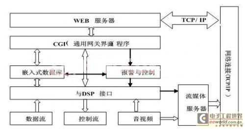
FPGA (installed with Linux system) completes the video server function (and can provide some data interfaces). The compressed video signal is forwarded through streaming media to the corresponding management device (PC, etc.) through the network interface. The data signal is directly transmitted to the management device through the TCP/IP protocol. The implementation of the video server is shown in Figure 4.

Figure 4 Video server implementation block diagram
Software
1) DSP subsystem software design. This part includes the design of CPLD/FPGA logic control software and interface driver, where the control logic implements the logic circuit through VHDL language; interface driver includes: video interface driver, audio interface driver, serial port driver, and AD circuit interface driver. Because DSP is mainly responsible for data collection and processing, the logic control part is mainly completed in FPGA.
2) FPGA subsystem software design. In addition to completing some data interfaces, the main task of the FPGA part is to complete the streaming media and data server functions and various control logics (such as linkage logic, etc.). Its overall structure is shown in Figure 4.
Current status and development trends of research at home and abroad
With the rapid development of information and network technology in modern society, remote monitoring has gradually replaced on-site monitoring, and active research has been carried out both at home and abroad. The traditional video monitoring system adopts C/S mode, and due to the limitations of technological development, it can only conduct on-site monitoring and simple alarm information transmission, and cannot realize long-distance transmission of video signals. It is very difficult to understand the specific situation of the front end and confirm the event, which invisibly reduces the stability and security of the system. Especially now, in order to improve labor productivity and enhance competitiveness, enterprises have adopted a large number of unattended modes in the normal production process. For some industries, such as substations, remote and real-time monitoring is a prerequisite for the safe operation of industry systems. At present, the Web-based B/S mode is one of the development directions of the monitoring system. The B/S mode monitoring system consists of a browser, an application server and a database server. The remote monitoring system based on the embedded Web server and the B/S mode monitoring provides an effective way for the networking and miniaturization of the monitoring system. Embedded network monitoring has become one of the key directions for the future development of the monitoring system. Its addition avoids the defects of on-site monitoring, saves management costs, and improves system stability and security. Therefore, remote monitoring will have a very optimistic prospect in the future market and has a broad market.
Innovations and features of the project
Innovation
The equipment uses embedded technology and an open network platform. By configuring a variety of sensors and transmitters, it can collect and control the analog data and status parameters of the scene in real time, and can implement remote monitoring of the monitoring site. For example, the camera can transmit the scene image through the network, and access, control and configure these cameras through the web page, and realize the transmission of video signals in the local area network, wide area network or international Internet through ISDN, PSTN, or xDSL routers. High-quality MPEG4 images can be transmitted at 25 (PAL) frames per second on the 10/100 Base-T network through Category 5 cables, optical fibers or wireless media.
The remote controller will integrate multiple functions such as on-site data collection, conversion of multiple communication protocols, fault alarm, emergency control, intelligent linkage, and embedded WEB configuration page.
feature
It supports audio, video and on-site data collection, emergency alarm, remote software upgrade and update, XML interface and .NET platform seamless integration, multi-user simultaneous access, multi-level password authentication mechanism, strong adaptability, good security, high precision, high reliability, high intelligence, good maintainability, and can automatically work according to pre-set parameters when separated from the host computer, and the parameters can be adjusted remotely in real time.
Previous article:Design of suspension motion control system based on 32-bit DSP and motor driver chip
Next article:Probing Analog and Digital Signals with a Mixed Signal Oscilloscope
- Popular Resources
- Popular amplifiers
- Huawei's Strategic Department Director Gai Gang: The cumulative installed base of open source Euler operating system exceeds 10 million sets
- Analysis of the application of several common contact parts in high-voltage connectors of new energy vehicles
- Wiring harness durability test and contact voltage drop test method
- Sn-doped CuO nanostructure-based ethanol gas sensor for real-time drunk driving detection in vehicles
- Design considerations for automotive battery wiring harness
- Do you know all the various motors commonly used in automotive electronics?
- What are the functions of the Internet of Vehicles? What are the uses and benefits of the Internet of Vehicles?
- Power Inverter - A critical safety system for electric vehicles
- Analysis of the information security mechanism of AUTOSAR, the automotive embedded software framework
 Professor at Beihang University, dedicated to promoting microcontrollers and embedded systems for over 20 years.
- LED chemical incompatibility test to see which chemicals LEDs can be used with
- Application of ARM9 hardware coprocessor on WinCE embedded motherboard
- What are the key points for selecting rotor flowmeter?
- LM317 high power charger circuit
- A brief analysis of Embest's application and development of embedded medical devices
- Single-phase RC protection circuit
- stm32 PVD programmable voltage monitor
- Introduction and measurement of edge trigger and level trigger of 51 single chip microcomputer
- Improved design of Linux system software shell protection technology
- What to do if the ABB robot protection device stops
- Allegro MicroSystems Introduces Advanced Magnetic and Inductive Position Sensing Solutions at Electronica 2024
- Car key in the left hand, liveness detection radar in the right hand, UWB is imperative for cars!
- After a decade of rapid development, domestic CIS has entered the market
- Aegis Dagger Battery + Thor EM-i Super Hybrid, Geely New Energy has thrown out two "king bombs"
- A brief discussion on functional safety - fault, error, and failure
- In the smart car 2.0 cycle, these core industry chains are facing major opportunities!
- The United States and Japan are developing new batteries. CATL faces challenges? How should China's new energy battery industry respond?
- Murata launches high-precision 6-axis inertial sensor for automobiles
- Ford patents pre-charge alarm to help save costs and respond to emergencies
- New real-time microcontroller system from Texas Instruments enables smarter processing in automotive and industrial applications
- How to choose a suitable water level sensor?
- [Xianji HPM6750 Review] + Software simulation IIC reads the temperature and humidity sensor values
- In fact, Valentine's Day 20200214 was cancelled
- This problem occurs when setting up the stm8 environment. What is the reason? Thank you
- dsp28335 data space
- [Xianji HPM6750 Review 8] Detailed description of the small twists and turns encountered by SPI peripherals
- MSP430 MCU Development Record (16)
- I posted a thread about icebabycool. He didn't answer the question but laughed at me instead of showing my low IQ. Please punish this kind of rogue behavior severely.
- Help with POE design issues
- [Voice and vision module based on ESP32S3] Material unpacking—ESP32S3 BOX

 THS4601IDR


 京公网安备 11010802033920号