With the popularization and development of Ethernet technology, the communication rate of Ethernet has gradually increased from 100M to 1G and even 10G, and its communication rate has met the throughput required by common signal processors. DSP devices that were previously used only for signal processing have gradually added Ethernet communication functions. Common DSP devices such as TI's DM642, C6455, C6678, etc. have Ethernet interfaces, which greatly facilitates the design of some signal processing boards that require high-speed communication interfaces. This paper uses TI's high-end DSP device TMS320 C6455 on a processing board to complete the high-speed Ethernet communication function between the signal processing board and the human-machine interface. The system test results show that the Ethernet communication interface implemented by C6455 fully meets the system design requirements, and the system has the advantages of simple composition and high system integration.
1 Hardware Platform
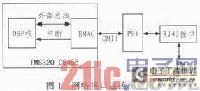
The main hardware of the signal processing board includes two high-speed DACs, two high-speed ADCs, a Xilinx V5 FPGA and a TMS320 C6455 DSP processor. The network communication interface mainly includes C6455, PHY chip and RJ45 interface, as shown in Figure 1. The EMAC interface of C6455 is connected to the PHY chip on the signal board in GMII mode, supporting Gigabit duplex communication mode.
2 Introduction to C6455 EMAC interface
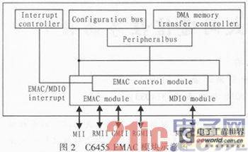
The EMAC interface of C6455 is mainly composed of three parts, including MDIO module, EMAC module and EMAC control module. Among them, the MDIO module completes the configuration and management of the Ethernet physical layer chip through the serial communication interface specified by the 802.3 protocol: the EMAC module is responsible for the sending and receiving of Ethernet data packets; the EMAC control module acts as a bridge between the DSP core and the EMAC interface to realize the control of the EMAC module and the MDIO module by the DSP core.
As shown in Figure 2, the EMAC interface is connected to the DSP core through the peripheral bus provided by C6455. The configuration bus in the peripheral bus provides the DSP core with access to the EMAC register, and the data bus completes the exchange of Ethernet communication packets between the DSP core and the EMAC interface. In addition, the EMAC control module integrates the 18 interrupt signals generated by the EMAC module and the MDIO module, and provides an interrupt signal to the interrupt controller of the C6455, which becomes the 17th system event of the C6455 processor. After receiving the interrupt signal, the DSP core of the C6455 determines the interrupt source by querying the interrupt status register provided by the EMAC control module.
Packet Buffer Descriptors play a key role in the network communication of C6455. The information exchange between the application and the EMAC interface is mainly realized through packet buffer descriptors. The structure of the packet buffer descriptor is shown in Figure 3. Each packet buffer descriptor is 16 bytes in size. The meanings of each field are as follows: Next Descriptor Pointer indicates the pointer to the next descriptor, so that multiple packet buffer descriptors can form a one-way linked list; Buffer Pointer indicates the pointer to the memory space for receiving or sending data. According to the pointer, the EMAC module starts the internal DMA engine to put the data into the internal FIFO for sending, or reads it from the internal FIFO to the address for application processing; Buffer Offset indicates the distance from the address pointed by the Buffer Pointer to the valid data; Buffer Length indicates the size of the data pointed to by the buffer; Flags indicates whether the data pointed to by the buffer is the start packet or the end packet of the application data packet; Packets Length indicates the total length of the application data packet. The application packet may be composed of one or more packet buffer descriptors.

The EMAC module processes packet buffer descriptors in the form of a linked list. The first address of the descriptor linked list needs to be written into the head descriptor register of the EMAC. The EMAC starts from the descriptor pointed to by the head descriptor register and processes all the descriptors in the linked list one by one until it encounters a descriptor whose Next Descriptor Pointer is zero. When all the descriptors in the linked list are processed, the EMAC sends an interrupt to the DSP core and writes the address of the last descriptor processed into the send/receive completion register. The DSP core synchronizes the sending or receiving of data with the EMAC through the interrupt and completion register.
3 Ethernet communication program design
The Ethernet communication program designed in this paper is based on the DSP operating system DSP/BIOS provided by TI, which provides clock timing, task synchronization, hardware interrupt management and other functions. As shown in Figure 4, the Ethernet communication program is mainly composed of the DSP/BIOS operating system, the network driver and the user program. The DSP/BIOS operating system provides timing, task synchronization and other services for other modules; the network driver completes the Ethernet communication function; the user program is responsible for interpreting and executing the commands and data sent by the human-machine interface. The network driver mainly includes the Ethernet hardware driver and several basic network protocols, including ICMP, ARP and UDP protocols. Among them, the design of the Ethernet hardware driver is the focus of the article, which mainly includes the MDIO driver and the EMAC driver. The MDIO driver completes the interaction between the C6455 EMAC and the physical chip, while the EMAC driver provides an Ethernet communication interface for the user program.

3.1 Design of MDIO driver module
The MDIO module is mainly responsible for searching, configuring and monitoring external Ethernet physical transceiver chips. This module mainly includes the following parts: MDIO hardware initialization; PHY chip search and configuration; PHY chip status monitoring. The detailed design description is as follows:
3.1.1 MDIO hardware initialization
MDIO hardware initialization includes the following steps:
1) Read the MACSEL bit in the C6455 device status register (DEVSTFAT) to determine the connection mode between the EMAC and the PHY chip. The C6455 EMAC and PHY chip on the signal processing board involved in this article are connected using the GMII method.
2) Initialize the MDIO state machine and set the state machine to the initialization state.
3) Configure the MDIO to access the clock of the PHY chip and enable the MDIO module.
3.1.2 PHY chip search and configuration
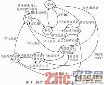
Since there is no definite time for the search process of the PHY chip, the implementation of the PHY chip search and configuration is implemented using a state machine. The state machine completes the corresponding operation and updates to the next state every 100 ms according to the queried state of the PHY chip, as shown in Figure 5. The search for the PHY chip goes through processes such as chip reset and communication rate auto-negotiation, and finally establishes an Ethernet physical layer connection with the communication peer.
3.1.3 PHY chip status monitoring
After the Ethernet physical layer link is established, the link status may change due to the user unplugging the network cable, the other end machine changing the communication interface rate, etc. Therefore, the MDIO module needs to monitor the network at regular intervals. The status monitoring module designed in this paper queries the network status every 100 ms by the DSP/BIOS operating system. Once the status monitoring program finds that the link status has changed, it enters the corresponding processing flow according to the different reasons causing the link change. The process is shown in the "link connection" state and the corresponding transfer state in Figure 5.
3.2 Design of EMAC driver module
The EMAC driver module is mainly responsible for the reception and transmission of Ethernet data packets. It is the main component of the Ethernet driver. This module mainly includes the following parts: EMAC hardware initialization; EMAC receiving module; EMAC sending module. The detailed design description of each module is as follows:
3.2.1 EMAC hardware initialization
The main purpose of EMAC hardware initialization is to put the EMAC module in the ready state. At this time, EMAC can receive and send Ethernet data packets. The initialization process mainly includes the following steps:
1) Disable EMAC interrupts, reset EMAC's HDP registers, statistics registers, etc., set EMAC's MAC address, and attach callback functions provided by the application.
2) Allocate corresponding packet buffer descriptors to the sending module and receiving module according to requirements, and initialize the packet buffer descriptor of the receiving module to point to the data receiving storage block provided by the application. The Ethernet driver designed in this paper allocates 32 packet buffer descriptors to the receiving module, 480 packet buffer descriptors to the sending module, and a total of 64 storage blocks to the sending and receiving modules, each with a size of 4,096 bytes. Figure 6 shows the relationship between the receiving descriptor and the receiving storage block after the receiving module is initialized.
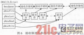
As shown in Figure 6, the EMAC_Ch_Struct structure is used in this paper to cover the linked list pointers used by the receiving module. Among them, DescQueue represents an empty receive storage block linked list. When EMAC receives a piece of data, it starts the DMA inside EMAC, puts the data into the storage block pointed to by the current descriptor, and notifies the application of data arrival through an interrupt; pDescFirst points to the first address of the receive descriptor linked list, pDescLast points to the last address of the receive descriptor linked list; pDescRead points to the first available descriptor; pDescWrite points to the last available descriptor;
3) Configure whether MAC is a multicast address, enable Ethernet interrupt, and EMAC is in a ready state.
3.2.2 EMAC receiving module
The EMAC receiving module is mainly driven by EMAC interrupts. When the EMAC hardware receives one or more packet data, it will send a receive completion interrupt to the DSP core. After receiving the interrupt, the DSP core calls the receive data callback function provided by the application to process the received data and returns a free storage block to the interrupt service program. The interrupt service program relinks the storage block to the receive storage block list to complete the receive data flow.
3.2.3 EMAC send module
The EMAC send module is mainly composed of a send interface function ethSendPacket (char*Buffer, int Length). The user program completes the Ethernet data transmission by calling this function. In the function parameters, Buffer represents the data that the application needs to send, and Length represents the length of the send data. The function first copies the data in the Buffer to a free storage block and adds the storage block to the WaitQueue queue shown in Figure 7. The WaitQueue queue represents the storage block waiting to be added to the EMAC send queue (DescQueue). The ethSendPacket function then checks whether the EMAC send queue DescQueue has a free send descriptor. If so, the storage block in the WaitQueue list is added to the DeseQueue. The EMAC hardware will send the data in the DescQueue through the corresponding descriptor.
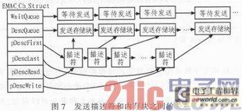
When the data transmission is completed, EMAC sends a transmission completion interrupt to the DSP core. The transmission completion interrupt service routine removes the storage block after transmission from the DescQueue and returns it to the application, and then sets the used transmission descriptor to the idle state for use when sending data next time.
3.3 Design of ARP/ICMP/UDP network protocol module
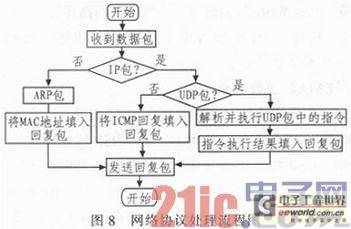
In order to complete network communication with the host computer, the signal processor must also provide basic network communication protocols. In the design of this paper, three network protocols, ARP/ICMP/UDP, are mainly provided. The ARP protocol mainly completes the conversion between the IP address and MAC address of the signal processor; the ICMP protocol mainly completes the network connectivity test between the signal processor and the host computer; the UDP protocol mainly completes the communication of actual instructions and data.
The design of these network protocol modules is simplified in this paper. The main idea of the design is to parse the packet format of the three protocols, and encapsulate the corresponding response packet according to different protocols and send it to the host computer. In the design of the UDP protocol, in order to ensure that the data can be accurately delivered to the host computer, CRC check and error retransmission mechanism are added. The protocol processing flow is shown in Figure 8.
4 Conclusion In
this paper , TMS320C6455 is used as the core chip. Through the research on C6455 EMAC hardware and referring to the relevant Ethernet drivers, the design of C6455 Ethernet communication program is completed. The results show that the Ethernet driver and network protocol module designed in this paper can better meet the basic needs of the processor for real-time and efficient data communication, save the modification of the signal processor hardware, reduce the complexity of the system, and provide a good reference for the development of other projects.
However, in the process of testing the network throughput performance of the signal processor, it is found that the actual network throughput rate is still far from the theoretical rate of Gigabit Ethernet. How to further optimize the architecture of the driver and the algorithm of the key data structure in order to further improve the network throughput rate is the next research direction of the author.
Previous article:Design and implementation of high-speed communication interface based on FPGA+DSP
Next article:Fingerprint recognition block diagram and solution using TI's low-power C5x DSP
- Popular Resources
- Popular amplifiers
- Red Hat announces definitive agreement to acquire Neural Magic
- 5G network speed is faster than 4G, but the perception is poor! Wu Hequan: 6G standard formulation should focus on user needs
- SEMI report: Global silicon wafer shipments increased by 6% in the third quarter of 2024
- OpenAI calls for a "North American Artificial Intelligence Alliance" to compete with China
- OpenAI is rumored to be launching a new intelligent body that can automatically perform tasks for users
- Arm: Focusing on efficient computing platforms, we work together to build a sustainable future
- AMD to cut 4% of its workforce to gain a stronger position in artificial intelligence chips
- NEC receives new supercomputer orders: Intel CPU + AMD accelerator + Nvidia switch
- RW61X: Wi-Fi 6 tri-band device in a secure i.MX RT MCU
 Professor at Beihang University, dedicated to promoting microcontrollers and embedded systems for over 20 years.
- LED chemical incompatibility test to see which chemicals LEDs can be used with
- Application of ARM9 hardware coprocessor on WinCE embedded motherboard
- What are the key points for selecting rotor flowmeter?
- LM317 high power charger circuit
- A brief analysis of Embest's application and development of embedded medical devices
- Single-phase RC protection circuit
- stm32 PVD programmable voltage monitor
- Introduction and measurement of edge trigger and level trigger of 51 single chip microcomputer
- Improved design of Linux system software shell protection technology
- What to do if the ABB robot protection device stops
- CGD and Qorvo to jointly revolutionize motor control solutions
- CGD and Qorvo to jointly revolutionize motor control solutions
- Keysight Technologies FieldFox handheld analyzer with VDI spread spectrum module to achieve millimeter wave analysis function
- Infineon's PASCO2V15 XENSIV PAS CO2 5V Sensor Now Available at Mouser for Accurate CO2 Level Measurement
- Advanced gameplay, Harting takes your PCB board connection to a new level!
- Advanced gameplay, Harting takes your PCB board connection to a new level!
- A new chapter in Great Wall Motors R&D: solid-state battery technology leads the future
- Naxin Micro provides full-scenario GaN driver IC solutions
- Interpreting Huawei’s new solid-state battery patent, will it challenge CATL in 2030?
- Are pure electric/plug-in hybrid vehicles going crazy? A Chinese company has launched the world's first -40℃ dischargeable hybrid battery that is not afraid of cold
- Portable energy storage power supply-Nanxin Semiconductor enters the market with strength
- Summary of the characteristics of 5 wireless transmission protocols for the Internet of Things
- Can dual 12V power supplies be used in parallel?
- MSP-FET430UIF driver cannot be installed in Windows 7
- Use GD32 to make a music spectrum to practice
- Zhou Ligong ZDS1104 and Macosin Oscilloscope STO1104C Operation Video (Transferred)
- Energy Harvesting with MSP430 FRAM Microcontrollers
- Live FAQ|Maxim IO-Link Solution
- How to solve the problem that a pin of the HuaDa MCU always outputs a high-level pulse after power-on reset/hardware reset?
- 【Qinheng RISC-V core CH582】WeChat applet controls lighting

 AD5533ABC-1


 京公网安备 11010802033920号