Basic knowledge of high frequency circuits
|
|
|

|

|
| Figure 1-(a) Low frequency circuit | Figure 1-(b) High frequency circuit |
Figure (a) The low-frequency circuit is driven by a constant voltage. Even if the load impedance changes, the output voltage remains constant. The relationship between the amplifier's output impedance Zo and the load's impedance ZL is Zo|
The high-frequency circuit in Figure b is a power-driven circuit. The unit of the signal is power, and the most effective power that can be taken out of the load is when Zo=ZL, that is, when the impedance is matched (Impendance matting). Therefore, the consideration method for low-frequency circuit analysis is the same as that for high-frequency circuit analysis.
|
|
|
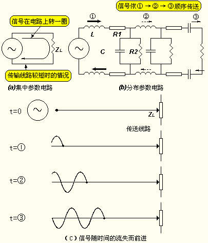
The figure on the right shows the analysis method of the concentrated constant circuit and the distributed constant circuit using the transmission path as an example.
|

Previous article:Overview of Oscillation Circuit
Next article:Half-wave synchronous detection circuit composed of switching circuit
- High signal-to-noise ratio MEMS microphone drives artificial intelligence interaction
- Advantages of using a differential-to-single-ended RF amplifier in a transmit signal chain design
- ON Semiconductor CEO Appears at Munich Electronica Show and Launches Treo Platform
- ON Semiconductor Launches Industry-Leading Analog and Mixed-Signal Platform
- Analog Devices ADAQ7767-1 μModule DAQ Solution for Rapid Development of Precision Data Acquisition Systems Now Available at Mouser
- Domestic high-precision, high-speed ADC chips are on the rise
- Microcontrollers that combine Hi-Fi, intelligence and USB multi-channel features – ushering in a new era of digital audio
- Using capacitive PGA, Naxin Micro launches high-precision multi-channel 24/16-bit Δ-Σ ADC
- Fully Differential Amplifier Provides High Voltage, Low Noise Signals for Precision Data Acquisition Signal Chain
- Innolux's intelligent steer-by-wire solution makes cars smarter and safer
- 8051 MCU - Parity Check
- How to efficiently balance the sensitivity of tactile sensing interfaces
- What should I do if the servo motor shakes? What causes the servo motor to shake quickly?
- 【Brushless Motor】Analysis of three-phase BLDC motor and sharing of two popular development boards
- Midea Industrial Technology's subsidiaries Clou Electronics and Hekang New Energy jointly appeared at the Munich Battery Energy Storage Exhibition and Solar Energy Exhibition
- Guoxin Sichen | Application of ferroelectric memory PB85RS2MC in power battery management, with a capacity of 2M
- Analysis of common faults of frequency converter
- In a head-on competition with Qualcomm, what kind of cockpit products has Intel come up with?
- Dalian Rongke's all-vanadium liquid flow battery energy storage equipment industrialization project has entered the sprint stage before production
- Allegro MicroSystems Introduces Advanced Magnetic and Inductive Position Sensing Solutions at Electronica 2024
- Car key in the left hand, liveness detection radar in the right hand, UWB is imperative for cars!
- After a decade of rapid development, domestic CIS has entered the market
- Aegis Dagger Battery + Thor EM-i Super Hybrid, Geely New Energy has thrown out two "king bombs"
- A brief discussion on functional safety - fault, error, and failure
- In the smart car 2.0 cycle, these core industry chains are facing major opportunities!
- The United States and Japan are developing new batteries. CATL faces challenges? How should China's new energy battery industry respond?
- Murata launches high-precision 6-axis inertial sensor for automobiles
- Ford patents pre-charge alarm to help save costs and respond to emergencies
- New real-time microcontroller system from Texas Instruments enables smarter processing in automotive and industrial applications
- Does the AD18 library have this kind of package? Do I have to draw it myself?
- 77Ghz single-chip millimeter wave sensor enables automatic parking
- What is the function of this circuit in ESP32_Audio_kit?
- Please ask about the problem in TI official application manual - boost principle
- TFT touch screen power supply problem
- STM32CubeMX uses LL library to set timer to control gpio flip
- What's the meaning of "Red umbrellas and white poles, lie down on the board together after eating"?
- 【Jiajiabao】 esp32s2 tcp+mqtt running
- I encountered several problems in the multisim simulation of the bandpass filter circuit, as shown in the figure. Which forum friend can give me some advice?
- No padsnet.err file is generated during synchronization. What is the reason?

 Signal Integrity and Power Integrity Analysis (Eric Bogatin)
 開關電源專業英語


 京公网安备 11010802033920号