Electrical signal chains come in many forms. They can consist of different electrical components, including sensors, actuators, amplifiers, analog-to-digital converters (ADCs), digital-to-analog converters (DACs), and even microcontrollers. The accuracy of the entire signal chain plays a decisive role. To improve accuracy, the individual errors in each signal chain must first be identified and minimized. Due to the complexity of the signal chain, this analysis can be a difficult task. This article introduces a signal chain error budget calculation tool for precision digital-to-analog converters (DACs). The article will describe the individual error effects of the components connected to the DAC. Finally, it will show step-by-step how to use the tool to identify and correct these problems.
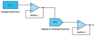
The precision digital-to-analog converter (DAC) error budget calculator provides accurate and easy-to-use calculations to help developers select the most appropriate components for a specific application. Since the digital-to-analog converter (DAC) does not usually appear alone in the signal chain, but is connected to a reference voltage and an operational amplifier (for example, as a reference buffer), it is important to value and summarize these additional components and their individual errors. To better understand this concept, we first look at the individual error effects of the main components, as shown in Figure 1.

Figure 1. Key elements of the digital-to-analog converter (DAC) signal chain.
There are four main error effects on the reference voltage. The first is related to the initial accuracy (initial error), which is manifested by the instability of the output voltage measured during production testing at 25°C (specified temperature). In addition, there are errors related to the temperature coefficient (temperature coefficient error), load regulation error, and line regulation error. Initial accuracy and temperature coefficient errors have the greatest impact on the total error.
In an op amp, input offset voltage error and resistor value error have the greatest impact. Input offset voltage error refers to the small voltage difference forced on the input to obtain a zero voltage output. Gain error is caused by the resistance error of the corresponding resistor used to set the closed-loop gain. Other errors are caused by bias current, power supply rejection ratio (PSRR), open-loop gain, input offset current, CMRR offset, and input offset voltage drift.
For the digital-to-analog converter (DAC) itself, various types of errors are given in the datasheet, such as integral nonlinearity (INL) error, which is related to the difference between the ideal output voltage and the actual output voltage measured for a given input code. Other error types are gain error, offset error, and gain temperature coefficient error. Sometimes these are combined together to form the total unadjusted error (TUE). TUE is related to all measured output DAC errors, namely INL, offset and gain errors, as well as output drift over the supply voltage and temperature range.
Because the different error sources are usually uncorrelated, the most accurate way to calculate the total error in a signal chain is the statistical squared error method:

Gathering the errors of individual components is usually a tedious task, but now we can use the Error Budget Calculator to simplify this task and obtain the same accurate calculation results.

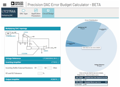
Figure 2. Representation of error effects in the ADI Error Budget Calculator.
Steps for Using the Precision Digital-to-Analog Converter (DAC) Error Budget Calculator
First, use the error budget calculator to select from three types of digital-to-analog converters (DACs): voltage output DACs, multiplying DACs, and 4 mA to 20 mA current source DACs. Next, set the temperature range and power supply voltage ripple required for the error calculation, which will play a decisive role in the PSRR error. After entering these values, the calculator will generate a graph showing the individual error contributions of each component in the signal chain, as shown in Figure 2.
The total error in this example is mainly affected by the reference voltage. This signal chain can be improved by using a more accurate reference block.
The integrated resistor of the DAC is responsible for the comparison of the internal inverter amplifier, thereby improving the accuracy and playing a decisive role in the total error of the DAC. In a DAC without an integrated resistor or an internal inverter amplifier, these parameters can be set individually, as shown in Figure 2.
The Error Budget Calculator is reliable and easy to use, making it easier to create precision digital-to-analog converter (DAC) signal chains and quickly evaluate design trade-offs.
About the Author
Thomas Brand joined Analog Devices in Munich, Germany in 2015 while still completing his master's degree. After graduation, he joined Analog Devices as a trainee. In 2017, he became a field applications engineer. Thomas supports large industrial customers in Central Europe and specializes in the field of Industrial Ethernet. He graduated in electrical engineering at the University of Cooperative Education in Mosbach, Germany, and then obtained a master's degree in international sales at the University of Applied Sciences in Constance, Germany. Contact: thomas.brand@analog.com.
Previous article:Student Zone—ADALM2000 Experiment: Source Follower (NMOS)
Next article:Low-noise, low-power DAQ solutions for seismology and energy exploration applications
- Popular Resources
- Popular amplifiers
- High signal-to-noise ratio MEMS microphone drives artificial intelligence interaction
- Advantages of using a differential-to-single-ended RF amplifier in a transmit signal chain design
- ON Semiconductor CEO Appears at Munich Electronica Show and Launches Treo Platform
- ON Semiconductor Launches Industry-Leading Analog and Mixed-Signal Platform
- Analog Devices ADAQ7767-1 μModule DAQ Solution for Rapid Development of Precision Data Acquisition Systems Now Available at Mouser
- Domestic high-precision, high-speed ADC chips are on the rise
- Microcontrollers that combine Hi-Fi, intelligence and USB multi-channel features – ushering in a new era of digital audio
- Using capacitive PGA, Naxin Micro launches high-precision multi-channel 24/16-bit Δ-Σ ADC
- Fully Differential Amplifier Provides High Voltage, Low Noise Signals for Precision Data Acquisition Signal Chain
- LED chemical incompatibility test to see which chemicals LEDs can be used with
- Application of ARM9 hardware coprocessor on WinCE embedded motherboard
- What are the key points for selecting rotor flowmeter?
- LM317 high power charger circuit
- A brief analysis of Embest's application and development of embedded medical devices
- Single-phase RC protection circuit
- stm32 PVD programmable voltage monitor
- Introduction and measurement of edge trigger and level trigger of 51 single chip microcomputer
- Improved design of Linux system software shell protection technology
- What to do if the ABB robot protection device stops
- Car key in the left hand, liveness detection radar in the right hand, UWB is imperative for cars!
- After a decade of rapid development, domestic CIS has entered the market
- Aegis Dagger Battery + Thor EM-i Super Hybrid, Geely New Energy has thrown out two "king bombs"
- A brief discussion on functional safety - fault, error, and failure
- In the smart car 2.0 cycle, these core industry chains are facing major opportunities!
- The United States and Japan are developing new batteries. CATL faces challenges? How should China's new energy battery industry respond?
- Murata launches high-precision 6-axis inertial sensor for automobiles
- Ford patents pre-charge alarm to help save costs and respond to emergencies
- New real-time microcontroller system from Texas Instruments enables smarter processing in automotive and industrial applications
- Sandia Labs develops battery failure early warning technology to detect battery failures faster
- Analysis of EMI radiation signal strength
- Research on the Development of Radio Frequency Filter Materials Industry
- Working Principle of Solar Street Lights
- [RVB2601 Creative Application Development] + A Preliminary Study on Connecting to Alibaba Cloud
- [RVB2601 Creative Application Development] Practice 3 - External DHT11 Display of Temperature and Humidity
- Top 5 Microcontroller Board Features
- MSA-AIAG-Manual 4
- Solution to power supply problem of MCU based on SE8510
- Basics | Learn the basics of "amplifier" in 5 minutes
- Fresh and hot, aircraft cabin pressure and temperature data recorded by SensorTile.box

 OPA121KU/2K5


 京公网安备 11010802033920号