Overview of each team’s solutions
The method proposed in the literature [1] is that the trapezoidal distortion can be eliminated by performing a linear correction on each row of extracted road positions, and the coefficient of the linear compensation can be determined experimentally. However, the experimental method is relatively complicated and cannot eliminate the barrel distortion.
Reference [2] produced an image calibration plate, as shown in Figure 1.

The principle is: the shaded part in Figure 1(a) is the position of the vehicle body. Many black lines are pasted on the calibration board at equal intervals. After taking a photo of the calibration board, the relationship between the actual position and the position in the image can be known. This method will have a large error because the black lines have a certain width.
Reference [3] adopts a non-uniform row acquisition scheme. The so-called non-uniform row acquisition is the opposite of uniform row acquisition. In uniform row acquisition, the rows acquired by the AD module are evenly distributed in the image output by the camera. Non-uniform row acquisition means that the rows acquired by the AD module are non-uniformly distributed in the original image according to a certain rule, and this rule is to ensure that the acquired image is not distorted in the vertical direction (the direction of the center axis of the car) with the actual scene. Then the lateral distortion coefficient of each row is determined.

As shown in Figure 2, when non-uniform data is collected, the data collected at a distance is dense, while the data collected at a nearby location is sparse. Since the camera installation method is often changed during the experiment, in order to determine the optimal depression angle and optimal height, recalibration is required every time the camera is changed. This solution is not very convenient. Reference [4] established a light path geometric model diagram, as shown in Figure 3.

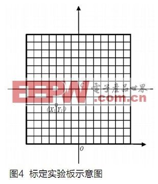
Experimental plan: Measure the height H of the camera frame fixing screw and the deflection angle (pitch angle) θ of the camera center relative to the vertical rod. Since the calculation of the optical center is completely determined by these two data and the distance S from the proximal end to the fixing rod (that is, the distance S0 from the bumper to the fixing rod and the distance S' from the proximal end to the bumper are added together, and the distance S from the proximal end black line to the camera fixing rod can also be directly measured on the experimental board), the more accurate the better. Draw a vertical line with a length of H from point O to point A, draw a horizontal line AB, intercept AD with a length of S, and make a ray DB through point O that is θ with the vertical line and intersects AB at C. D draw DE perpendicular to OC through D, and make OC the perpendicular bisector of DE, connect BE and extend it, intersecting OC and O', then O' is the optical center. From the figure, it can be calculated that the distance from O' to the bottom edge is H', and the pitch angle remains unchanged. Place the experimental board vertically, make a square calibration area with a side length of A1, that is, the DE plane in Figure 3, and place the camera horizontally facing the center C of the experimental board. The distance between the camera frame fixing screw and the experimental board is H1. Read out the corresponding pixel points of the feature points on the calibration test board. The relationship between (X, Y) and pixel points (U, V) in Figure 4 can be obtained (U is the number of rows and V is the number of columns).

Since the relationship between the experimental plane and the real visual field plane is purely geometric, this part of the conversion function relationship can be derived geometrically. The formula is relatively complicated and will not be listed here one by one.
The biggest drawback of this formula is that there are many trigonometric functions such as sin() and cos(), but it takes a lot of time for the microcontroller to do such calculations, so trigonometric functions and square root calculations should be avoided as much as possible. Moreover, if a wide-angle lens is used or the camera is mounted low, point B will be far away from point A and point B cannot be found. Therefore, this method is not universal. The experiment itself is also relatively complicated.
The experimental method used in the literature [5] is: draw a series of small squares on a white board in advance. The smaller the squares, the higher the accuracy. Then mark the center black thick line to determine the placement of the car and the center of the image. As shown in Figure 5, the corresponding pixel coordinates of each feature point can be directly read out to establish a corresponding relationship.

The experimental scheme is very intuitive, but its operation is not necessarily easy. Because the camera has a wide field of view, the required correction network is also large, and it is difficult to ensure that the grid lines drawn on it are absolutely horizontal or vertical.
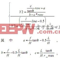
Reference [6] uses geometric mathematical modeling to derive the relationship between the imaging coordinates of the image captured by the camera and the actual world coordinates of the scene. The coordinate transformation relationship is as follows:

After the camera is installed and fixed, c/tanθ, a, b, c, h and h/cosθ are all constants. This method is relatively good, but it requires knowing f, L, and H. The manufacturer will provide these three parameters, but they may not be accurate. θ is also difficult to measure accurately, and it cannot solve the problem of barrel distortion.
Previous article:Low power consumption design of wireless sensor based on MSP430
Next article:System Design for Detecting Fiber Bragg Grating Sensors Using Matched Grating Demodulation
- Popular Resources
- Popular amplifiers
- High signal-to-noise ratio MEMS microphone drives artificial intelligence interaction
- Advantages of using a differential-to-single-ended RF amplifier in a transmit signal chain design
- ON Semiconductor CEO Appears at Munich Electronica Show and Launches Treo Platform
- ON Semiconductor Launches Industry-Leading Analog and Mixed-Signal Platform
- Analog Devices ADAQ7767-1 μModule DAQ Solution for Rapid Development of Precision Data Acquisition Systems Now Available at Mouser
- Domestic high-precision, high-speed ADC chips are on the rise
- Microcontrollers that combine Hi-Fi, intelligence and USB multi-channel features – ushering in a new era of digital audio
- Using capacitive PGA, Naxin Micro launches high-precision multi-channel 24/16-bit Δ-Σ ADC
- Fully Differential Amplifier Provides High Voltage, Low Noise Signals for Precision Data Acquisition Signal Chain
- LED chemical incompatibility test to see which chemicals LEDs can be used with
- Application of ARM9 hardware coprocessor on WinCE embedded motherboard
- What are the key points for selecting rotor flowmeter?
- LM317 high power charger circuit
- A brief analysis of Embest's application and development of embedded medical devices
- Single-phase RC protection circuit
- stm32 PVD programmable voltage monitor
- Introduction and measurement of edge trigger and level trigger of 51 single chip microcomputer
- Improved design of Linux system software shell protection technology
- What to do if the ABB robot protection device stops
- Huawei's Strategic Department Director Gai Gang: The cumulative installed base of open source Euler operating system exceeds 10 million sets
- Download from the Internet--ARM Getting Started Notes
- Learn ARM development(22)
- Learn ARM development(21)
- Learn ARM development(20)
- Learn ARM development(19)
- Learn ARM development(14)
- Learn ARM development(15)
- Analysis of the application of several common contact parts in high-voltage connectors of new energy vehicles
- Wiring harness durability test and contact voltage drop test method
- The first article GD32VF103C START development board unboxing running lights
- How to eliminate the influence of gravity acceleration on accelerometer
- 【Development and application based on NUCLEO-F746ZG motor】14. Parameter configuration - motor parameter configuration
- Impedance matching principle
- How to earn points?
- MSP430 programmer and emulator
- [ESP32-S2-Kaluga-1 Review] 5. Image display, button and RGB LED operation
- What is the switching power supply with constant power output?
- 530M power supply quality resources one-click download, limited time free points
- How to obtain a package in an existing PCB diagram

 M38510/10104SGX


 京公网安备 11010802033920号