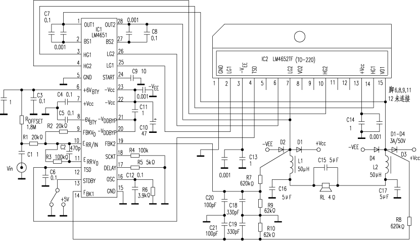
The 125W Class D subwoofer power amplifier circuit designed with the newly launched LM4651 and LM4652 of National Semiconductor is shown in the figure. The output power of the amplifier is 125W under the total harmonic distortion THD=1%, the load impedance RL=4Ω, the input signal Vin (rms) maximum level is 3V, the input signal bandwidth is 10~150Hz, the ambient temperature is 50℃, and the power supply voltage is ±20V.
The LM4651 in 28-pin DIP package is a PWM control/driver IC with built-in oscillator, PWM comparator, error amplifier, feedback amplifier, level shifter and high-end driver, low-end driver and undervoltage, overheating, short circuit and overmodulation protection circuits. LM4652 is a half-bridge power MOSFET IC in a 15-pin (6, 8, 9, {11}, {12} pins are not connected) TO-220 package. The breakdown voltage of the four MOSFETs is V(BR)DSS=50V, the drain current ID=10A, the on-state resistance RDS(ON)=200mΩ (typical value), and the turn-on voltage VGS(th)=0.85V (typical value).
The oscillator frequency fosc in LM4651 is 1×10⁹/(4000+Rosc), where Rosc=R6=3.9kΩ, so fosc=125kHz. The input audio signal is input to the error amplifier with a gain of 7.5V/V (i.e. 17.5dB) through C1, R1 and pin 10. The half-bridge switch outputs at IC27 and {15} are filtered by RC filters and fed back to IC1 {14} and {19} pins. After passing through the internal feedback measurement amplifier, they are output from pin 9 to pin 10 to provide a single-ended feedback signal for the error amplifier. The audio input signal is compared with the triangle wave generated by the oscillator, and a square wave pulse with a duty factor proportional to the input audio signal level is generated at the output of the PWM comparator to drive the power MOSFET in IC2. The switch outputs at IC27 and {15} pins are low-pass filtered by L1, C16 and L2, C17 to drive the speaker.
The resistor R4 at IC1 {18} pin is used as a short-circuit current limiter. When R4=100kΩ, the short-circuit current level is not less than 10A; the resistor R5 on the {17} pin is used to set the dead time; the capacitor C9 on the {24} pin is used to set the start delay time (1 second), and when the {13} pin (STOBY) is set to logic "1" or 5V, the standby function is performed, the pulse width modulation is stopped, and the power switch in the LM4652 is turned off, consuming only very low current. As long as the junction temperature of IC2 reaches 150℃, the output of its 4th pin is fed back to the {12} pin of IC1, and the thermal shutdown function can be performed.

Previous article:Wideband high frequency power amplifier
Next article:What ruined the op amp?
- Popular Resources
- Popular amplifiers
- High signal-to-noise ratio MEMS microphone drives artificial intelligence interaction
- Advantages of using a differential-to-single-ended RF amplifier in a transmit signal chain design
- ON Semiconductor CEO Appears at Munich Electronica Show and Launches Treo Platform
- ON Semiconductor Launches Industry-Leading Analog and Mixed-Signal Platform
- Analog Devices ADAQ7767-1 μModule DAQ Solution for Rapid Development of Precision Data Acquisition Systems Now Available at Mouser
- Domestic high-precision, high-speed ADC chips are on the rise
- Microcontrollers that combine Hi-Fi, intelligence and USB multi-channel features – ushering in a new era of digital audio
- Using capacitive PGA, Naxin Micro launches high-precision multi-channel 24/16-bit Δ-Σ ADC
- Fully Differential Amplifier Provides High Voltage, Low Noise Signals for Precision Data Acquisition Signal Chain
- LED chemical incompatibility test to see which chemicals LEDs can be used with
- Application of ARM9 hardware coprocessor on WinCE embedded motherboard
- What are the key points for selecting rotor flowmeter?
- LM317 high power charger circuit
- A brief analysis of Embest's application and development of embedded medical devices
- Single-phase RC protection circuit
- stm32 PVD programmable voltage monitor
- Introduction and measurement of edge trigger and level trigger of 51 single chip microcomputer
- Improved design of Linux system software shell protection technology
- What to do if the ABB robot protection device stops
- Allegro MicroSystems Introduces Advanced Magnetic and Inductive Position Sensing Solutions at Electronica 2024
- Car key in the left hand, liveness detection radar in the right hand, UWB is imperative for cars!
- After a decade of rapid development, domestic CIS has entered the market
- Aegis Dagger Battery + Thor EM-i Super Hybrid, Geely New Energy has thrown out two "king bombs"
- A brief discussion on functional safety - fault, error, and failure
- In the smart car 2.0 cycle, these core industry chains are facing major opportunities!
- The United States and Japan are developing new batteries. CATL faces challenges? How should China's new energy battery industry respond?
- Murata launches high-precision 6-axis inertial sensor for automobiles
- Ford patents pre-charge alarm to help save costs and respond to emergencies
- New real-time microcontroller system from Texas Instruments enables smarter processing in automotive and industrial applications
- Looking for PD Sink controller solution
- Making solar inverters more reliable than the sun
- EEWORLD University - Basic Knowledge of Welding
- micropython update: 2020.4
- [Fudan Micro FM33LG0 Series Development Board Review] Fudan Microchip uses J-Scope waveform software to accelerate product development
- How to make a circle of vias regularly?
- VTran reveals how to improve the accuracy of geomagnetic vehicle inspections
- Use of isolation amplifier chip ISO124P
- Boost and buck-boost DC-DC converters help wireless charging designs
- I never dared to think about not adding return vias before!

 LT1468CDD#TRPBF


 京公网安备 11010802033920号