In view of the characteristics of electrical control products, this paper discusses several design methods of commonly used input/ output circuits of single-chip microcomputers , which has practical guiding significance for rationally designing electrical control systems, improving the interface capabilities of circuits, and enhancing system stability and anti-interference capabilities.
introduction
The various control signals used in traditional electrical equipment must be converted into digital signals that match the input/output ports of the single-chip microcomputer. The user equipment must input various control signals to the single-chip microcomputer, such as limit switches, operating buttons, selection switches, travel switches, and the switch quantities output by other sensors, etc., and convert them into signals that the single-chip microcomputer can receive and process through the input circuit. The output circuit should convert and amplify the weak current control signal sent by the single-chip microcomputer to the strong output signal required on site to drive the actuators of the controlled equipment such as power tubes, solenoid valves, relays, contactors, motors, etc., which can facilitate the use of the actual control system.
1 Input circuit design
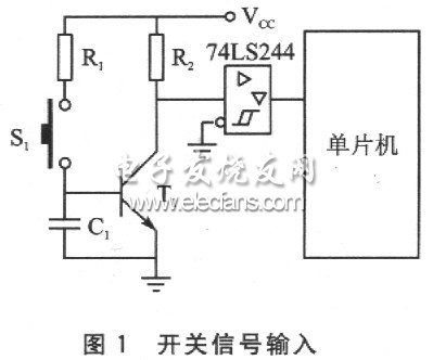
Generally, the input signal will eventually be input to the single-chip microcomputer in the form of a switch. According to engineering experience, the control command of the switch input is much better when it is at a low level than at a high level, as shown in Figure 1. When the switch S1 is pressed, the command signal is at a low level, and when the switch S1 is not pressed, the level output to the single-chip microcomputer is at a high level. This method has a strong noise resistance.

If we consider that the TTL level voltage is low and is easily interfered by the outside world during long-distance transmission, we can increase the input signal to +24 V and convert the high voltage signal into a TTL signal at the entrance of the microcontroller. This high voltage transmission method not only improves the noise resistance, but also makes the switch contact good and reliable, as shown in Figure 2. Among them, D1 is a protection diode with a reverse voltage of ≥50 V.
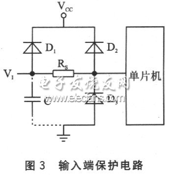
In order to prevent external spike interference and electrostatic influence from damaging the input pin, a pulse-proof diode can be added to the input end to form a resistor bidirectional protection circuit, as shown in Figure 3. The forward conduction voltage drop UF≈0.7 V of diodes D1, D2, and D3, and the reverse breakdown voltage UBR≈30 V. No matter what polarity of the destructive voltage appears at the input end, the protection circuit can limit the amplitude of the voltage to the range that the input end can withstand. That is: when a positive pulse appears in VI~VCC, D1 is forward-conducted; when a negative pulse appears in V1~VCC, D2 is reversely broken down; when a positive pulse appears between VI and ground, D2 is reversely broken down; when a negative pulse appears between V1 and ground, D3 is forward-conducted, and the diode plays a clamping protection role. The buffer resistor RS is about 1.5~2.5kΩ, which forms an integral circuit with the input capacitor C, and delays the external induced voltage for a period of time. If the interference voltage exists for less than t, the effective voltage borne by the input end will be much lower than its amplitude; if the time is longer, D1 is turned on. The current forms a certain voltage drop on RS, thereby reducing the input voltage value.

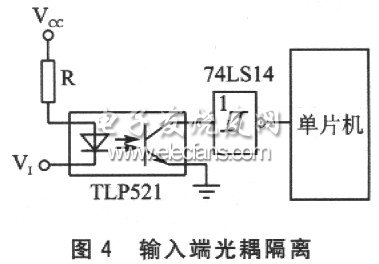
In addition, a commonly used input method is to use an optocoupler isolation circuit. As shown in Figure 4, R is the input current limiting resistor, which limits the current of the light-emitting diode in the optocoupler to 10-20 mA. The input end is coupled by optical signals and is electrically completely isolated. At the same time, the forward impedance of the light-emitting diode is low, while the internal resistance of the external interference source is generally high. According to the voltage division principle, the interference noise that the interference source can feed to the input end is very small, and no ground interference or other crosstalk will be generated, which enhances the anti-interference ability of the circuit.


Under the premise of meeting the functional requirements, the simplest solution to improve the reliability of the microcontroller input terminal is to connect a capacitor in parallel between the input terminal and the ground to absorb interference pulses, or to connect a metal film resistor in series to limit the peak current flowing into the port.
Previous article:FPGA Design Computer Application Based on EDA Technology
Next article:Introduction to common input and output circuits of single chip microcomputers
Recommended ReadingLatest update time:2024-11-16 15:34


- Popular Resources
- Popular amplifiers
-
 Wireless Sensor Network Technology and Applications (Edited by Mou Si, Yin Hong, and Su Xing)
 -
 Modern Electronic Technology Training Course (Edited by Yao Youfeng)
 -
 Modern arc welding power supply and its control
 -
 Small AC Servo Motor Control Circuit Design (by Masaru Ishijima; translated by Xue Liang and Zhu Jianjun, by Masaru Ishijima, Xue Liang, and Zhu Jianjun)
- High signal-to-noise ratio MEMS microphone drives artificial intelligence interaction
- Advantages of using a differential-to-single-ended RF amplifier in a transmit signal chain design
- ON Semiconductor CEO Appears at Munich Electronica Show and Launches Treo Platform
- ON Semiconductor Launches Industry-Leading Analog and Mixed-Signal Platform
- Analog Devices ADAQ7767-1 μModule DAQ Solution for Rapid Development of Precision Data Acquisition Systems Now Available at Mouser
- Domestic high-precision, high-speed ADC chips are on the rise
- Microcontrollers that combine Hi-Fi, intelligence and USB multi-channel features – ushering in a new era of digital audio
- Using capacitive PGA, Naxin Micro launches high-precision multi-channel 24/16-bit Δ-Σ ADC
- Fully Differential Amplifier Provides High Voltage, Low Noise Signals for Precision Data Acquisition Signal Chain
- Innolux's intelligent steer-by-wire solution makes cars smarter and safer
- 8051 MCU - Parity Check
- How to efficiently balance the sensitivity of tactile sensing interfaces
- What should I do if the servo motor shakes? What causes the servo motor to shake quickly?
- 【Brushless Motor】Analysis of three-phase BLDC motor and sharing of two popular development boards
- Midea Industrial Technology's subsidiaries Clou Electronics and Hekang New Energy jointly appeared at the Munich Battery Energy Storage Exhibition and Solar Energy Exhibition
- Guoxin Sichen | Application of ferroelectric memory PB85RS2MC in power battery management, with a capacity of 2M
- Analysis of common faults of frequency converter
- In a head-on competition with Qualcomm, what kind of cockpit products has Intel come up with?
- Dalian Rongke's all-vanadium liquid flow battery energy storage equipment industrialization project has entered the sprint stage before production
- Allegro MicroSystems Introduces Advanced Magnetic and Inductive Position Sensing Solutions at Electronica 2024
- Car key in the left hand, liveness detection radar in the right hand, UWB is imperative for cars!
- After a decade of rapid development, domestic CIS has entered the market
- Aegis Dagger Battery + Thor EM-i Super Hybrid, Geely New Energy has thrown out two "king bombs"
- A brief discussion on functional safety - fault, error, and failure
- In the smart car 2.0 cycle, these core industry chains are facing major opportunities!
- The United States and Japan are developing new batteries. CATL faces challenges? How should China's new energy battery industry respond?
- Murata launches high-precision 6-axis inertial sensor for automobiles
- Ford patents pre-charge alarm to help save costs and respond to emergencies
- New real-time microcontroller system from Texas Instruments enables smarter processing in automotive and industrial applications
- How to import images into DDR in CCSv5
- PID control algorithm implementation in C language
- MSP430F149 and PC serial port communication problem
- machine.ADC added in stm32
- Try it, can you access this website of ST?
- I found the fish's partner - [Electronic Components Artwork]
- ESD protection and elimination methods in switching power supply design and production
- 【TI mmWave Radar Review】+3D Profile Test
- I thought it was washing the phone, but it turned out to be washing the phone
- Medium and low pressure MODS pipes

 Wireless Sensor Network Technology and Applications (Edited by Mou Si, Yin Hong, and Su Xing)


 京公网安备 11010802033920号