Timing and protocol are two key points in digital system debugging, and they are also where logic analyzers can play their most valuable role. How can we use a logic analyzer to quickly complete wiring configuration and collect data? Here we take the IIC protocol as an example for a practical demonstration.
The logical relationship of the digital system is the key in the communication research and development process, which directly affects whether the entire equipment system can work normally.
Although oscilloscopes can also perform some digital signal analysis, they are limited by the number of channels (usually only 4 channels) and the storage depth (small). Logic analyzers can reach 34 channels, with a maximum recording depth of 2G, and combined with data compression algorithms, they greatly improve the efficiency of engineers' test timing analysis.
Below, we will take IIC as an example to share the logic analyzer test steps.
1. Preparation
The tests mainly include the object under test, logic analyzer, computer, and IIC protocol signal.
Use the standard power adapter to power the logic analyzer and press the power button. Connect the instrument to the PC with a USB cable, open the software, and check whether there is "Online" on the software interface. Connect the IIC protocol (amplitude 3.2V, frequency 50KHz), use the measurement line PODA A1 to SCL, A0 to SDA, and make sure the signal ground wire is connected.
2. IIC bus settings
1. Click on the bus name to modify the bus name. It is recommended not to have duplication.
2. The bus name should be related to the channel meaning.
3. Do not add the same bus, the software will filter them out.
4. Do not add a bus without a channel.
5. Delete useless buses in time to make it look more concise.
The setting effect is shown in Figure 1: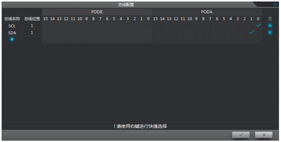
Figure 1 IIC channel opening
3. IIC sampling parameter settings
1. Sampling mode: the difference between synchronous and asynchronous, the advantages of synchronous sampling;
2. Sampling frequency: the sampling frequency is generally set to 4~5 times of the measured signal. When protocol decoding is required, it needs to be more than 20 times. If the sampling rate is not enough, decoding errors will occur. Synchronous sampling should be used when the measured signal frequency is high;
3. Storage depth: channel multiplexing, segmented storage, compressed storage, recording mode (real-time storage);
4. Threshold voltage: generally set to 1/2 (MAX+MIN);
5. Filter setting: bus filtering, filtering the burr signal of one sampling cycle. Channel filtering, filtering 1~2 sampling cycles. Bus filtering and channel filtering are both hardware filtering.
The setting effect is shown in Figure 2: 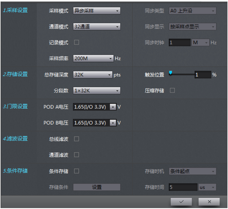
Figure 2 Parameter setting
IV. IIC trigger and decoding setting
1. Set the name to custom;
2. Input bus corresponds to the channel;
3. Set the address bit of the bus;
The setting effect is shown in Figure 3 and Figure 4: 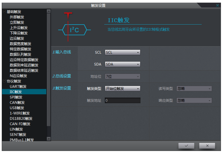
Figure 3 Trigger setting 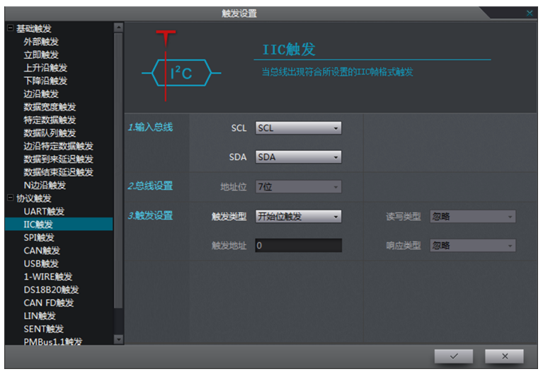
Figure 4 Property configuration
V. IIC decoding analysis results
Start to collect and store a section of data for analysis.
1. The data segment area reflects the waveform and results of the specific data analysis;
2. The waveform display setting can be used to adjust the waveform observation method;
3. The specific frame propagation content generated at different times can be observed through waveform zooming;
4. The timetable display area will logically analyze and transform the content of the entire data segment.
The test effect is shown in Figure 5: 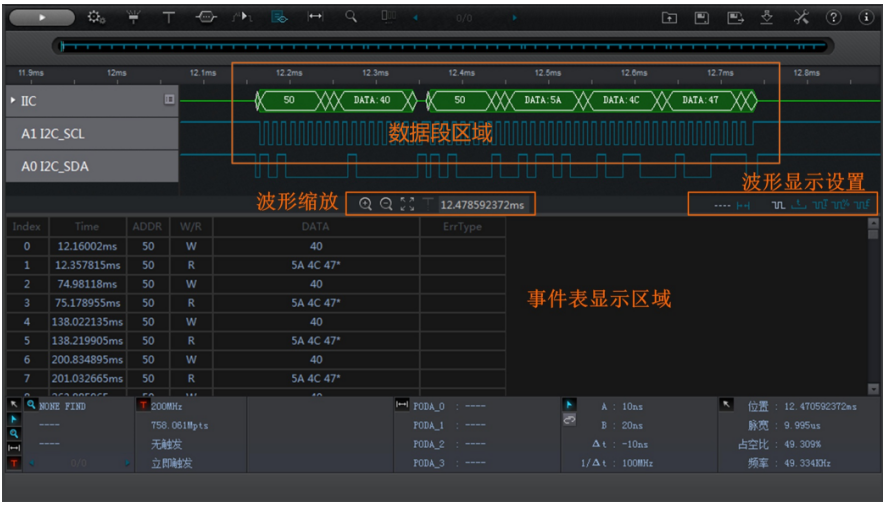
Figure 5 Decoding Analysis
VI. IIC Decoding Data Search
1. Search bus: IIC;
2. Start time: Ds, A, B;
3. End time: Dp, A, B;
4. Compare frame types: You can choose by yourself;
5. Data: You can enter the decimal, hexadecimal, and octal data of the corresponding frame type.
The setting effect is shown in Figure 6: 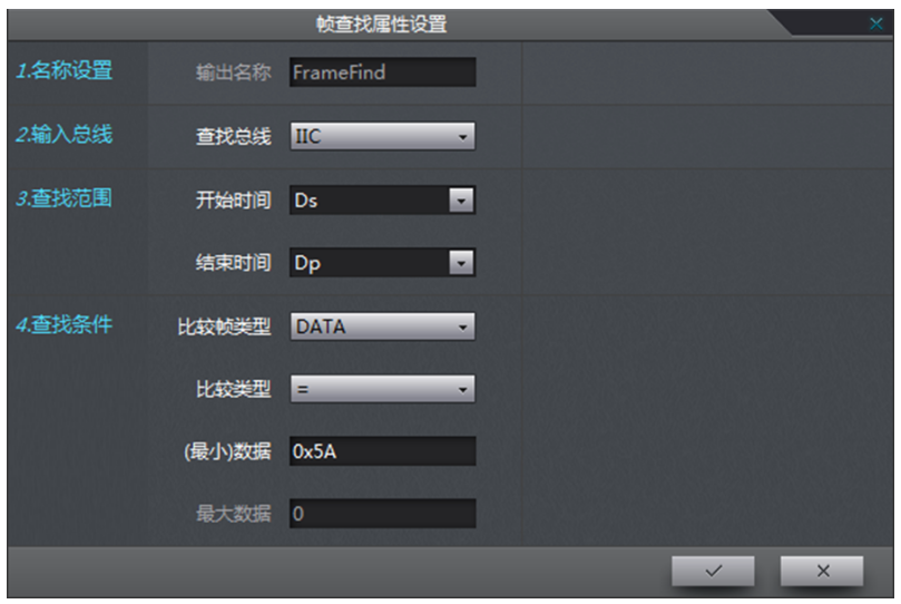
Figure 6 Frame search attribute setting
VII. Accurate positioning of decoded data
After completing the setting, you can display it by searching for specific search types, and the effect is shown in Figure 7: 
Figure 7 Search result display
There are 68 search results in this search, and each search result can be observed by the following operations. The effect is shown in Figure 8: 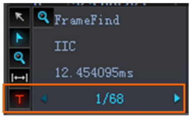
Figure 8 Search result data analysis
Zhiyuan Electronics Logic Analyzer has ultra-large capacity storage, intelligent filtering storage, high-fidelity uninterrupted real-time recording, efficient protocol analysis platform, trigger search diversification, flexible parameter measurement, and can locate specific waveform data when the system runs wrong. For digital circuit developers and testers, logic analyzers can use logic analyzers to perform precise state or timing analysis on circuits to detect and analyze errors in circuit design, so as to quickly locate and solve problems.
Previous article:Trending and Tracking: Introducing Two Useful Oscilloscope Diagnostic Tools
Next article:Tips for using IE browser to access the oscilloscope
- Popular Resources
- Popular amplifiers
- Keysight Technologies Helps Samsung Electronics Successfully Validate FiRa® 2.0 Safe Distance Measurement Test Case
- From probes to power supplies, Tektronix is leading the way in comprehensive innovation in power electronics testing
- Seizing the Opportunities in the Chinese Application Market: NI's Challenges and Answers
- Tektronix Launches Breakthrough Power Measurement Tools to Accelerate Innovation as Global Electrification Accelerates
- Not all oscilloscopes are created equal: Why ADCs and low noise floor matter
- Enable TekHSI high-speed interface function to accelerate the remote transmission of waveform data
- How to measure the quality of soft start thyristor
- How to use a multimeter to judge whether a soft starter is good or bad
- What are the advantages and disadvantages of non-contact temperature sensors?
- LED chemical incompatibility test to see which chemicals LEDs can be used with
- Application of ARM9 hardware coprocessor on WinCE embedded motherboard
- What are the key points for selecting rotor flowmeter?
- LM317 high power charger circuit
- A brief analysis of Embest's application and development of embedded medical devices
- Single-phase RC protection circuit
- stm32 PVD programmable voltage monitor
- Introduction and measurement of edge trigger and level trigger of 51 single chip microcomputer
- Improved design of Linux system software shell protection technology
- What to do if the ABB robot protection device stops
- Allegro MicroSystems Introduces Advanced Magnetic and Inductive Position Sensing Solutions at Electronica 2024
- Car key in the left hand, liveness detection radar in the right hand, UWB is imperative for cars!
- After a decade of rapid development, domestic CIS has entered the market
- Aegis Dagger Battery + Thor EM-i Super Hybrid, Geely New Energy has thrown out two "king bombs"
- A brief discussion on functional safety - fault, error, and failure
- In the smart car 2.0 cycle, these core industry chains are facing major opportunities!
- The United States and Japan are developing new batteries. CATL faces challenges? How should China's new energy battery industry respond?
- Murata launches high-precision 6-axis inertial sensor for automobiles
- Ford patents pre-charge alarm to help save costs and respond to emergencies
- New real-time microcontroller system from Texas Instruments enables smarter processing in automotive and industrial applications
- How to design PCB to achieve the best EMC effect
- TMS320C6748 Learning [Timer Learning]
- Vivado simulation issues
- Differential filter PCB layout needs to consider,,,
- Studying Things to Gain Knowledge 06: A Drop of Water Generator
- C port of pic16F877A
- Disassemble the aircraft black box and see which manufacturers' chips are inside
- MSP430 IO external interrupt programming example sharing
- Infineon's Home HVAC Solutions Invite You to Open Blind Box
- What is peak-to-peak value? Peak value? Effective value? Understanding these parameters makes amplifier selection so easy!

 ISL28414FBZ-T13


 京公网安备 11010802033920号