1 Introduction
Compared with mechanical buttons and resistive touch buttons, capacitive touch buttons are not only durable, low-cost, simple and easy to install, waterproof and anti-fouling, but also provide functions such as rollers and sliders. However, capacitive touch buttons also have many problems. Because there is no mechanical structure, all detections are small changes in electricity, so they are much more sensitive to various interferences. ST has launched a capacitive touch sensing solution based on the STM8 series 8-bit general-purpose microcontroller platform for home appliance applications, especially induction cooker applications. There is no need to add a dedicated touch chip. Capacitive touch sensing functions can be realized with only a simple peripheral circuit, which is convenient for customers to develop secondary development.
2 Solution Introduction
ST's capacitive touch button solution detects the capacitance change caused by human touch through the charging/discharging time of a resistor-capacitor network composed of a resistor and the capacitor CX of the sensing electrode. As shown in Figure 1, when a human hand presses, it is equivalent to connecting a capacitor CT in parallel to the sensing electrode, increasing the capacitance on the sensing electrode, and the charging and discharging time of the sensing electrode will increase, thereby detecting the state of the button. The sensing electrode can be directly drawn on the PCB board as a button, roller or slider application style, or it can be made into a spring component inserted on the PCB board, and its detection performance will not be affected even if it is separated by an insulating layer (glass, resin).
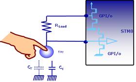
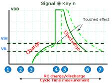
Figure 1 Working principle of STM8S capacitive touch button
The induction cooker heats food using the heating principle of magnetic field induction current. When heating, a strong magnetic field is generated by the coil under the panel. When the magnetic lines of force pass through the bottom of the pot made of a magnetic conductor, the pot cuts the alternating magnetic lines of force and generates eddy currents at the bottom of the pot, causing the bottom of the pot to heat up quickly, thus achieving the purpose of heating food. In this solution, the 44-pin STM8S105S4 is used as the main control chip of the key display board, controlling the scanning of 13 keys, the display of 24 LEDs and a 4-digit digital tube, the communication between I2C and the mainboard, and leaving a SWIM interface for engineers to debug (as shown in Figure 2).
The STM8S105S4 uses ST's advanced STM8 core, with a 3-stage pipeline Harvard structure, 3.0~5.5V operating voltage, an internal 16MHz RC that can provide the MCU with a 16MHz operating frequency, low power mode and peripheral clock shutdown function, and a total of 34 I/Os available. The STM8S105S4 has 2KB of RAM and 16KB of FLASH, as well as a 1KB EEPROM data memory with up to 300,000 erase and write times.
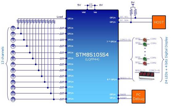
Figure 2 Principle of induction cooker keypad
3 Interference in the working environment of the induction cooker
1. Electromagnetic interference
When the induction cooker heats the pot, it also induces forward or reverse current on the induction electrodes on the circuit board, which will shorten or increase the charging and discharging time of the keys. This will have a great impact on the detection of the keys and may even cause false operations. Common methods use hardware shielding and zero-crossing detection to eliminate the impact of electromagnetic radiation on the keys.
Hardware Shield
In the STM8S solution, ST provides design specifications for sensing electrodes and routing and the Driven Shield function as shown in Figure 3 (providing the same driving signal as the button pin on the Shield line, the parasitic capacitance between the electrode and the Shield will not be charged or discharged), which can effectively reduce the impact of the parasitic capacitance of the sensing electrode routing on the button sensitivity.
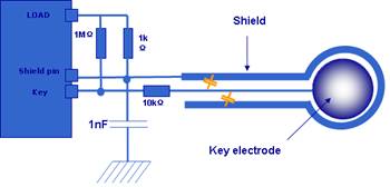
图3 Driven Shield
Zero crossing detection
1) Hardware zero-crossing detection
Zero-crossing point detection can be implemented by hardware. In the hardware design, a zero-crossing point hardware detection circuit as shown in FIG. 4 or FIG. 5 can be added. By judging the key state when the output at the B terminal is a high level, the touch key can be detected when the electromagnetic radiation is minimum.
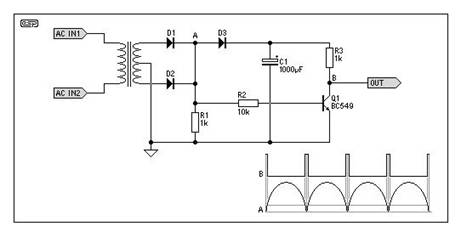
Figure 4 Hardware zero-crossing detection circuit 1
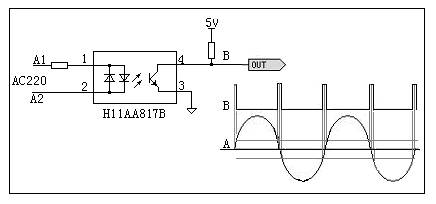
Figure 5 Hardware zero-crossing detection circuit 2
2) Software zero-crossing detection
Hardware zero-crossing detection increases the complexity of hardware circuit design and the cost of the solution. In our solution, we use software to perform zero-crossing detection for the working environment of the induction cooker, thereby reducing costs and effectively solving the interference of the main power circuit of the induction cooker on the touch buttons.
2. Grid interference
Because the quality of the domestic power grid varies, in some areas with poor quality, it is easy to affect the normal operation of the induction cooker touch buttons. If the power supply cannot be isolated, you will see the difference in Figure 6 (blue means no key, red means the key is pressed), and these figures are only when the induction cooker is not turned on. When the induction cooker is working, the electromagnetic radiation generated will make the signal seen more chaotic. In the experiment, it was found that the key effect can be significantly improved by isolating from the external power grid or using software filtering.
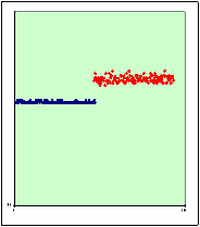
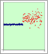
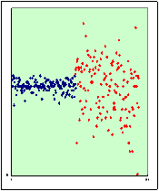
Figure 6: Good quality grid Poor quality grid 1 Poor quality grid 2
3. Impact of splashing water and oil
When using an induction cooker, water or oil often splashes onto the touch panel, which may cause false triggering of buttons. This solution uses a special software algorithm to reliably distinguish between water or oil splashes and finger pressing.
4. Environmental Adaptability
When the induction cooker is working, it will generate a lot of heat and moisture. The panel temperature/humidity and circuit board temperature/humidity will fluctuate in a wide range. As time goes by, the glass panel and PCB board will age to different degrees, thus affecting the accuracy of key detection. In ST's solution, an automatic calibration function is implemented, providing real-time environmental detection and realizing an environmental self-adaptation mechanism.
4 Conclusion
The solution provided by ST includes touch panel self-calibration, software filtering, software zero-crossing detection and environmental adaptation functions, and uses software algorithms to shield interference from various complex environments as much as possible, with low cost and reliable operation. Of course, in the application of other products, there will be some requirements that are different from the induction cooker environment. Here we only introduce some representative interferences, but as long as you understand the working principle of capacitive touch, there are still many ways to deal with various application situations.
Previous article:Characteristics of S-58LM20A sensor and its application in LED backlight compensation
Next article:MAX9635 Ambient Light Sensor with Integrated ADC
- High signal-to-noise ratio MEMS microphone drives artificial intelligence interaction
- Advantages of using a differential-to-single-ended RF amplifier in a transmit signal chain design
- ON Semiconductor CEO Appears at Munich Electronica Show and Launches Treo Platform
- ON Semiconductor Launches Industry-Leading Analog and Mixed-Signal Platform
- Analog Devices ADAQ7767-1 μModule DAQ Solution for Rapid Development of Precision Data Acquisition Systems Now Available at Mouser
- Domestic high-precision, high-speed ADC chips are on the rise
- Microcontrollers that combine Hi-Fi, intelligence and USB multi-channel features – ushering in a new era of digital audio
- Using capacitive PGA, Naxin Micro launches high-precision multi-channel 24/16-bit Δ-Σ ADC
- Fully Differential Amplifier Provides High Voltage, Low Noise Signals for Precision Data Acquisition Signal Chain
- Innolux's intelligent steer-by-wire solution makes cars smarter and safer
- 8051 MCU - Parity Check
- How to efficiently balance the sensitivity of tactile sensing interfaces
- What should I do if the servo motor shakes? What causes the servo motor to shake quickly?
- 【Brushless Motor】Analysis of three-phase BLDC motor and sharing of two popular development boards
- Midea Industrial Technology's subsidiaries Clou Electronics and Hekang New Energy jointly appeared at the Munich Battery Energy Storage Exhibition and Solar Energy Exhibition
- Guoxin Sichen | Application of ferroelectric memory PB85RS2MC in power battery management, with a capacity of 2M
- Analysis of common faults of frequency converter
- In a head-on competition with Qualcomm, what kind of cockpit products has Intel come up with?
- Dalian Rongke's all-vanadium liquid flow battery energy storage equipment industrialization project has entered the sprint stage before production
- Allegro MicroSystems Introduces Advanced Magnetic and Inductive Position Sensing Solutions at Electronica 2024
- Car key in the left hand, liveness detection radar in the right hand, UWB is imperative for cars!
- After a decade of rapid development, domestic CIS has entered the market
- Aegis Dagger Battery + Thor EM-i Super Hybrid, Geely New Energy has thrown out two "king bombs"
- A brief discussion on functional safety - fault, error, and failure
- In the smart car 2.0 cycle, these core industry chains are facing major opportunities!
- The United States and Japan are developing new batteries. CATL faces challenges? How should China's new energy battery industry respond?
- Murata launches high-precision 6-axis inertial sensor for automobiles
- Ford patents pre-charge alarm to help save costs and respond to emergencies
- New real-time microcontroller system from Texas Instruments enables smarter processing in automotive and industrial applications
- STMicroelectronics launches the second generation multi-zone time-of-flight sensor VL53L8
- EEWORLD University - Wildfire FreeRTOS Kernel Implementation and Application Development Practical Guide
- Teach you how to make a lithium battery fast charging charger
- Solution to the problem of not being able to generate electrical connection network using Harness in Altium Designer
- 【ufun learning】02 Concept and preliminary circuit design 1
- 【RT-Thread Reading Notes】Reflections on RT-Thread Chapters 7-8
- DC-DC chip LM2596SX-5.0/NOPB
- How does the lwip client let the server know that it has been shut down?
- Small car front-end 16W power supply design
- Bear Pie Huawei IoT operating system LiteOS bare metal driver transplantation 05-E53_SF1 expansion board driver and use

 Signal Integrity and Power Integrity Analysis (Eric Bogatin)


 京公网安备 11010802033920号