Currently, mobile wireless technology is transitioning to 4G LTE, and LTE networks have been commercially available in many countries and regions. According to a study by iSuppli, global shipments of smart terminals are expected to grow from 246.9 M pcs in 2010 to 506 M pcs in 2014. Major operators have also deployed 3G/4G base station networks in key areas to meet most of the users' voice and data service needs. However, in some cases, relying solely on base station network coverage still has problems.
For example, when a game is held in a stadium, users need to go online to share exciting videos and talk to others. Generally, the local 3G/4G base station can better support such voice and data services. However, during the game, there are usually a large number of users accessing the local base station network, which requires the local specific base station network to handle a large number of voice and data services in a certain period of time, causing the air interface of the base station to be blocked. The direct result is that the user's call quality is reduced, the line is often disconnected, and the Internet browsing speed is greatly reduced or there is no response for a long time.
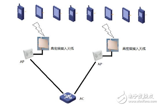
To address this problem, the current industry solution is to combine 802.11n wireless LAN technology with 3G/4G network technology to separate the user's data and voice services. That is, when the smart terminal user enters an area covered by a WIFI MIMO network, the data service is transferred to the WIFI network, and the cellular network focuses on voice services, so that the authorized frequency band can have a better call quality. This is the Cellular Offloading solution, as shown in Figure 1.

Figure 1: Schematic diagram of the Cellular Offloading solution.
Cellular Offloading technology requires that the same venue has both 3G/4G network signal coverage and WIFI network signal coverage. The 3G/4G base station is used for voice communication and the WIFI network is used for data services. A typical WIFI network structure includes: user client, antenna, access point, wireless controller AC and backbone network. The typical architecture is shown in Figure 2:

Figure 2: A typical WIFI network structure.
The current mainstream WIFI technology is the 802.11 a/b/g/n protocol. In actual applications, engineers are most concerned about how to achieve the best coverage and throughput while minimizing investment. This article will introduce how to use existing technologies and products to achieve a good coverage and air interface throughput in situations where users access in large quantities and at high density.
1. 802.11n MIMO technology
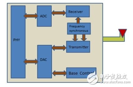
Traditional 802.11 a/b/g technology uses a single-input single-output system design as shown in Figure 3 (one TX and one RX, each with two antennas). This system uses one antenna to send and receive data, has a low throughput, and is usually used to avoid multipath reflections.

Figure 3: System design for traditional 802.11 a/b/g technology.
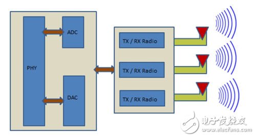
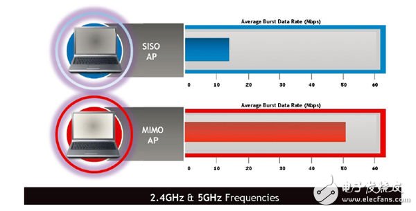
The system using MIMO spatial multi-stream multi-antenna technology uses multiple TX and RX to split a data stream and transmit and receive it through multiple independent antenna systems. This technology can greatly improve the air interface bandwidth and signal-to-noise ratio. When the TX segment has multiple antennas for transmission and the RX segment has multiple antennas for reception, a multi-antenna MIMO SDM (Spatial Division Multiplexing) space division multiplexing system is formed, as shown in Figure 4. In the space division system, because there are multiple streams, there will be interference between the data streams, which will cause the signal quality to deteriorate. Therefore, this system requires the radio part to perform special processing on the multi-stream signals. After adopting MIMO technology, the typical air interface rate of the system will be significantly improved, as shown in Figure 5.

Figure 4: MIMO SDM spatial division multiplexing system composed of multiple antennas.

Figure 5: Comparison of air interface rates of systems using SISO technology and MIMO technology.
2. Estimate the number of APs required for the venue and determine the interference situation
AP estimation method: A typical football stadium requires about 200~600 AP access points depending on the number of spectators. In general, 400~500K air interface traffic per user can better support user data services, such as browsing web pages, uploading or downloading videos. Currently, most terminals only support 802.11g air interface 54M services. Considering the multi-user access of AP in actual applications, the carrying capacity of a single AP is about 8~10M. Under different applications, the number of users accessing the WIFI AP network at the same time and the user groups using high-speed data services are different. For example, in a football stadium, there will be many users sharing photos and videos of exciting games. Each user needs 500K bandwidth, and the entire user group has a certain access ratio, so the number of users covered by each AP can be easily calculated.
Based on the number of users covered by each AP and the actual seat size of the venue, the coverage area of the AP antenna can be derived. The 802.11n 2.4 frequency band has 13 channels, and each channel is interlaced with each other. In order to ensure that there is no interference between channels, three non-overlapping channels 1, 6, and 11 are generally selected for network coverage. See Figure 6.

Figure 6: AP antenna coverage area.
The traditional AP+antenna system is not suitable for this occasion, because APs working on the same channel will interfere with each other. In a bowl-shaped stadium that requires hundreds of APs, if there is no antenna with a well-designed coverage angle, the mutual interference between APs is very serious, and each AP will spend a lot of resources to process the interference signals of adjacent channels. Therefore, specially designed antennas are the key to reducing interference between channels, as shown in Figure 7.

Figure 7: Specially designed antennas are key to reducing co-channel interference.
3. Choose an antenna with a suitable coverage angle
As mentioned above, interference between APs will cause a decrease in the user's air interface rate. There are generally two ways to reduce interference between APs in hardware, such as reducing AP transmit power and controlling the antenna pattern to reduce the wireless signal strength to neighboring APs. Controlling the antenna pattern means that the antenna is expected to have a narrowband coverage range, that is, the coverage area of each antenna only covers the target area, and the antenna gain outside the target area is required to decay rapidly, which can limit the number of users accessing this antenna, thereby reducing interference. There are contradictions here:
(1) The bandwidth and volume of the antenna are inversely proportional. The narrower the bandwidth of the antenna, the larger the antenna volume and the gain of the target coverage area. In actual applications, the stadium is bowl-shaped, and the user seats are arranged in a stepped manner, as shown in Figure 8. There should be no antennas in front of each row of seats that may potentially block the user's field of view. In addition, each stadium has its own unique industrial design. The antenna needs to be deployed in the stadium, and the industrial design of the antenna itself and the industrial design of the stadium also need to be well matched.

Figure 8
(2) Antenna bandwidth is proportional to gain. Antenna theory determines that the narrower the antenna bandwidth, the greater the gain of the antenna coverage area. However, too much gain has a potential impact on users. The North American FCC Committee stipulates that the intensity of the radio magnetic field in space cannot exceed the specified value. Under ideal narrowband coverage, the antenna gain will be very large, and combined with the AP's radiation power, it may exceed the FCC regulations.
Therefore, in practical applications, a balance must be struck between the gain, volume, and bandwidth of the antenna. After years of accumulation and multiple practical cases, PCTEL has found that the most suitable antenna indicators are:
Directional pattern angle: E plane (elevation) 35 degrees, A plane (azimuth) 55 degrees
Size: Antenna volume is approximately 35 cm x 35 cm
Gain: 2.4GHz 10dbi, 5Ghz 6dbi. With this size and coverage angle, the antenna gain can be 12dbi or higher, but according to the FCC regulations and the general AP transmission power, additional design needs to be added to the antenna to reduce the gain.
In some applications, a 35 cm x 35 cm enclosure may be too large. For applications with limited space, a smaller enclosure may be more appropriate, such as a 20 cm x 30 cm enclosure. However, this design will face several serious problems: first, the beam width will be too large, for example, 35 degrees in the E plane and 90 degrees in the A plane at 2.4G; second, the port isolation will drop by about 10db; third, the gain will drop; and fourth, the reflection caused by the close distance of the radiator will cause the radiation pattern to be deformed.
Application examples:
In recent years, PCTEL has provided antenna solutions for high-density applications for many famous venues around the world, including antennas (FP 2458-V6RPC) and related accessories. Typical venues include: Cowboys Stadium, Stanford Field, Wrigley Field, and XCEL Arena, etc., perfectly supporting actual on-site voice and data applications, such as the Cotton Bowl held at the Dallas Cowboys' Stadium on February 6, 2011. The PCTEL FP2458-V6RPC antenna covers WIFI 2.4-2.5GHz and 4.9-5.9GHz frequency bands, supports 6-port MIMO design, and the lobe width and gain are specially designed for high-density access scenarios and have been tested in practice. The shell material uses UL 94V-0 fireproof material to meet many design requirements of high-density access applications.

Fig. 9
Previous article:Integrating SAR Converter ADC Simplifies Signal Conditioning Path
Next article:MAX9075, MAX9077 Low-Cost, Ultra-Small, 3µA, Single-Supply Comparators
- Popular Resources
- Popular amplifiers
- High signal-to-noise ratio MEMS microphone drives artificial intelligence interaction
- Advantages of using a differential-to-single-ended RF amplifier in a transmit signal chain design
- ON Semiconductor CEO Appears at Munich Electronica Show and Launches Treo Platform
- ON Semiconductor Launches Industry-Leading Analog and Mixed-Signal Platform
- Analog Devices ADAQ7767-1 μModule DAQ Solution for Rapid Development of Precision Data Acquisition Systems Now Available at Mouser
- Domestic high-precision, high-speed ADC chips are on the rise
- Microcontrollers that combine Hi-Fi, intelligence and USB multi-channel features – ushering in a new era of digital audio
- Using capacitive PGA, Naxin Micro launches high-precision multi-channel 24/16-bit Δ-Σ ADC
- Fully Differential Amplifier Provides High Voltage, Low Noise Signals for Precision Data Acquisition Signal Chain
- LED chemical incompatibility test to see which chemicals LEDs can be used with
- Application of ARM9 hardware coprocessor on WinCE embedded motherboard
- What are the key points for selecting rotor flowmeter?
- LM317 high power charger circuit
- A brief analysis of Embest's application and development of embedded medical devices
- Single-phase RC protection circuit
- stm32 PVD programmable voltage monitor
- Introduction and measurement of edge trigger and level trigger of 51 single chip microcomputer
- Improved design of Linux system software shell protection technology
- What to do if the ABB robot protection device stops
- Car key in the left hand, liveness detection radar in the right hand, UWB is imperative for cars!
- After a decade of rapid development, domestic CIS has entered the market
- Aegis Dagger Battery + Thor EM-i Super Hybrid, Geely New Energy has thrown out two "king bombs"
- A brief discussion on functional safety - fault, error, and failure
- In the smart car 2.0 cycle, these core industry chains are facing major opportunities!
- The United States and Japan are developing new batteries. CATL faces challenges? How should China's new energy battery industry respond?
- Murata launches high-precision 6-axis inertial sensor for automobiles
- Ford patents pre-charge alarm to help save costs and respond to emergencies
- New real-time microcontroller system from Texas Instruments enables smarter processing in automotive and industrial applications
- Sandia Labs develops battery failure early warning technology to detect battery failures faster
- The disappearing boundary between MCU and MPU
- DS18B20 STM32G474 driver
- 【Fudan Micro FM33LC046N】Clock output test
- Python Basics: Dictionary Application
- A brief introduction to vehicle-mounted domain controllers
- Design of LED emergency lighting controller based on MSP430
- Disassembly of Taiwan TES-1316 temperature meter with temperature recording function
- Allwinner R528 core board and development board
- Pay attention when drawing and punching PCB!!
- Introduction to Multithreaded Programming in Embedded Systems

 TTLM124AJ/883


 京公网安备 11010802033920号