匹配传感器输出和 ADC 输入范围可能很难,尤其是要面对当今传感器所产生的多种输出电压摆幅时。本文为不同变化范围的差分、单端、单极性和双极性信号提供简便但高性能的 ADC 输入驱动器解决方案,本文的所有电路採用了 LTC2383-16 ADC 单独工作或与 LT6350 ADC 驱动器一起工作来实现 92dB SNR。
The LTC2383-16 is a low noise, low power, 1Msps, 16-bit ADC with a ±2.5V fully differential input range. The LT6350 is a rail-to-rail input and output, low noise, low power single-ended to differential converter/ADC driver with fast settling time. Using the LT6350, single-ended input ranges of 0V to 2.5V, 0V to 5V and ±10V can be easily converted to the ±2.5V fully differential input range of the LTC2383-16.
Fully differential drive
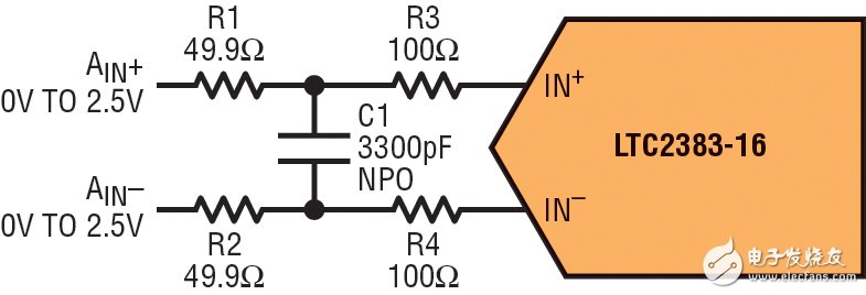
Figure 1 shows the basic building block used for all circuits described in this article. This basic building block is used to DC couple fully differential signals to the LTC2383-16 analog inputs. Resistors R1, R2, and capacitor C1 limit the input bandwidth to approximately 500kHz. Resistors R3 and R4 mitigate the effects of ADC input sampling spikes that can interfere with the sensor or ADC driver inputs.

Figure 1: Fully differential drive circuit
This circuit is useful for sensors with low impedance differential outputs. The common mode voltage driving AIN+ and AIN– must be equal to VREF/2 to meet the common mode input range requirement of the LTC2383-16.
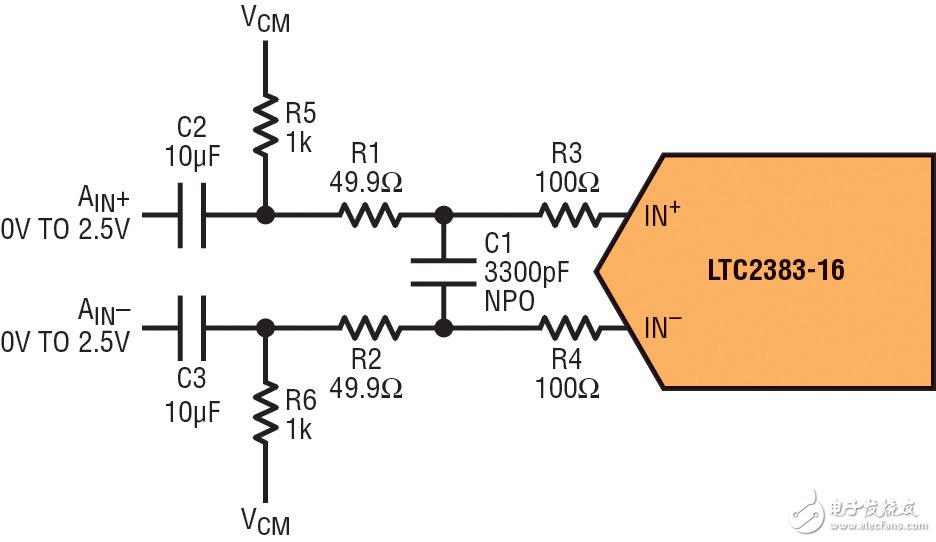
The circuit in Figure 1 can be AC coupled to match the common-mode voltage of the ADC input to the sensor if necessary. Simply bias AIN+ and AIN– to VCM (VCM=VREF/2) through a 1k resistor and couple the sensor output to AIN+ and AIN– through a 10µF capacitor, as shown in Figure 2.

Figure 2: AC-coupled fully differential drive circuit
When driving a low noise, low distortion ADC like the LTC2383-16, choosing the right components is critical to maintaining high performance. All resistors used in these circuits are relatively low value. This keeps noise low and settling time short. Metal film resistors are recommended to reduce distortion caused by self-heating. NPO capacitors are used for C1 because they have a low voltage coefficient, which minimizes distortion.
Single-ended to differential conversion
Of course, not all sensor outputs are differential. Here are some ways to drive the LTC2383-16 with a single-ended signal.
0V to 2.5V single-ended input
The circuit shown in Figure 3 converts a 0V to 2.5V single-ended signal to a fully differential ±2.5V signal. This circuit also features high impedance inputs so that it can be driven directly with most sensor outputs. As shown in Figure 2, the common mode voltage at VIN can be matched to the ADC by AC coupling VIN. The common mode voltage of the second amplifier is set at the +IN2 pin of the LT6350. The 32k point FFT in Figure 4 shows the performance of the LTC2383-16 combined with the LT6350 when using the circuit shown in Figure 3. The measured 92dB SNR and -107dB THD closely match the typical data sheet specifications of the LTC2383-16. This shows that the degradation of the ADC specifications, if any, is minimal after inserting the single-ended to differential converter in the signal path.

Figure 3: Single-ended to differential converter

Figure 4: FFT of the circuit in Figure 3
AMPLITUDE: Amplitude
0V to 5V single-ended input
If a wider input range is required, the negative input of the LT6350 can be driven, allowing the input voltage to be attenuated by the first stage of the LT6350. The circuit shown in Figure 5 converts a 0V to 5V single-ended signal to a ±2.5V differential signal that drives the input of the LTC2383-16. The input impedance of this circuit is equal to R7. Increasing the value of R7 increases the input impedance, making it easier to drive. The trade-off is that if R7 is increased above 4.99k, the noise and distortion will increase slightly, as shown in Table 1.

Figure 5: 0V to 5V single-ended driver
Table 1: Noise and distortion of 0V to 5V driver versus input resistance

±10V single-ended input
Some sensors provide output voltages above and below ground. The circuit shown in Figure 6 converts a ±10V ground referenced single-ended signal to a ±2.5V differential signal that drives the input of the LTC2383-16. The input impedance is still set by R7. Table 2 shows the noise and distortion of the Figure 6 circuit as a function of input impedance.

Figure 6: ±10V single-ended driver
Table 2: Noise and distortion vs. input resistance with ±10V drivers

in conclusion
The LTC2383-16 is a low power, low noise, 16-bit ADC that easily interfaces with a wide variety of sensor outputs, including a wide range of unipolar, bipolar, differential and single-ended signals.
Previous article:How to Use FPGA Clock Resources Correctly
Next article:Tips for designing key hardware circuits of MSP430
Recommended ReadingLatest update time:2024-11-15 17:17


- Popular Resources
- Popular amplifiers
-
 Siemens PLC Programming Technology and Application Cases (Edited by Liu Zhenquan, Wang Hanzhi, Yang Kun, etc.)
 -
 Siemens PLC from Beginner to Mastery with Color Illustrations (Yang Rui)
 -
 Siemens PLC Project Tutorial
 -
 Siemens S7-1200-PLC Programming and Application Tutorial (3rd Edition) (Edited by Shi Shouyong)
- High signal-to-noise ratio MEMS microphone drives artificial intelligence interaction
- Advantages of using a differential-to-single-ended RF amplifier in a transmit signal chain design
- ON Semiconductor CEO Appears at Munich Electronica Show and Launches Treo Platform
- ON Semiconductor Launches Industry-Leading Analog and Mixed-Signal Platform
- Analog Devices ADAQ7767-1 μModule DAQ Solution for Rapid Development of Precision Data Acquisition Systems Now Available at Mouser
- Domestic high-precision, high-speed ADC chips are on the rise
- Microcontrollers that combine Hi-Fi, intelligence and USB multi-channel features – ushering in a new era of digital audio
- Using capacitive PGA, Naxin Micro launches high-precision multi-channel 24/16-bit Δ-Σ ADC
- Fully Differential Amplifier Provides High Voltage, Low Noise Signals for Precision Data Acquisition Signal Chain
- LED chemical incompatibility test to see which chemicals LEDs can be used with
- Application of ARM9 hardware coprocessor on WinCE embedded motherboard
- What are the key points for selecting rotor flowmeter?
- LM317 high power charger circuit
- A brief analysis of Embest's application and development of embedded medical devices
- Single-phase RC protection circuit
- stm32 PVD programmable voltage monitor
- Introduction and measurement of edge trigger and level trigger of 51 single chip microcomputer
- Improved design of Linux system software shell protection technology
- What to do if the ABB robot protection device stops
- Huawei's Strategic Department Director Gai Gang: The cumulative installed base of open source Euler operating system exceeds 10 million sets
- Download from the Internet--ARM Getting Started Notes
- Learn ARM development(22)
- Learn ARM development(21)
- Learn ARM development(20)
- Learn ARM development(19)
- Learn ARM development(14)
- Learn ARM development(15)
- Analysis of the application of several common contact parts in high-voltage connectors of new energy vehicles
- Wiring harness durability test and contact voltage drop test method
- IMX6ULL Development Board - Text Editing Tool
- micropython update: 2020.3
- 【Experimental Case】Application of Power Amplifier in Microfluidic Chip Testing
- 【IoT Smart Home System】---Temperature and humidity data collection and upload (2)
- How to turn off the basic timer of STM32 HAL library
- Reading notes on the good book "Operational Amplifier Parameter Analysis and LTspice Application Simulation"
- AD7190 Issues
- Recruiting MCU sales engineers
- Ask questions about DAF equipment
- VS1053b cannot play music

 Siemens PLC Programming Technology and Application Cases (Edited by Liu Zhenquan, Wang Hanzhi, Yang Kun, etc.)
 Siemens S7-1200-PLC Programming and Application Tutorial (3rd Edition) (Edited by Shi Shouyong)


 京公网安备 11010802033920号