Synopsys's DC (Design Compiler) provides a synthesis optimization strategy for state machines. This process can be fully automatic or manual. This article discusses the implementation of two synthesis strategies.
1 Basic description of state machine
From a mathematical point of view, a finite state machine can be represented as a five-tuple M = (I, O, S, δ, λ). Among them: I and O represent the input and output respectively; S is the state vector; δ is the next state equation (δ: S ×I); λ is the output equation (λ: S ×I).
From the perspective of the actual implementation of the state machine, according to the output equation, the finite state machine can be divided into three categories:
a) The output is a function of the state vector and the input—Mealy-type state machine (λ: S ×I →O);
b) The output is only a function of the state vector—Moore-type state machine (λ: S →O);
c) The output is equal to the state vector—state output type state machine (λ: S = O).
The most commonly used state machines in practice are Mealy-type and Moore-type state machines.
From the perspective of circuits, a finite state machine is a system composed of flip-flops, registers, and combinational logic. Figure 1 shows the general structure of a finite state machine: a set of flip-flops that store state vectors and combinational logic that generates sub-states and outputs.

Figure 1 General structure of a finite state machine
1.1 State Table
In order to use DC's finite state machine optimization strategy, the original state machine must first be converted to a format described by a DC state table. This conversion can be done automatically or manually. Synopsys' state table provides a simple, process-independent way to describe a finite state machine. The following is an example of a state table
# State table body
Input PresentNext Output
Value State State Values
0 RESET RESET 00
1 RESET STATE1 01
0 STATE1 RESET 10
1 STATE1 STATE1 11
# Preferred state encoding
.encoding
RESET 2#00
STATE1 2#01
The body of the state table consists of rows, each describing a specific state transition of the state machine. Each row has 4 columns: input value, current state, next state, and output value. Some inputs can cause state transitions, while others cannot. It is easy to see the transition behavior of the state machine from the state table. The state table can also contain an optional section for giving the preferred state encoding, which can be given in decimal, binary, or hexadecimal.
The state table in the example includes: 1 input; 2 states, namely RESET and STATE1; 4 outputs, namely RESET and STATE1 are encoded as 0 and 1 respectively. The RESET state only switches to the STATE1 state when the input is 1, and the output becomes 01, while the STATE1 state only switches to the RESET state when the input is 0, and the output becomes 10.
In the example, all possible input, output and state combinations are used. If the state machine uses fewer states than the available encoding, you can create a state table that only contains the state transitions that need to be used, and other unspecified states are treated as don't care states.
1.2 State Vector
The state vector is one of the elements that describes the state machine and is specified by an ordered list of trigger instance names. The specified trigger stores ordered bit patterns that define the current state of the finite state machine at any given moment. A specific trigger bit pattern corresponds to a state. For example, ff1, ff2, ff3 are the instance names of the trigger, then the list {ff1 ff2 ff3} defines a 3-bit state vector, which can represent a finite state machine with no more than 8 states.
1.3 Status Code
The state encoding is another element that describes a state machine. The state encoding of a finite state machine symbolically defines the bit encodings of all legal states of the state machine. The encoding determines which bit patterns of the state vector represent legal states and which bit patterns can be treated as don't care states. Don't care states increase the likelihood that the tool will achieve good optimization results. For most designs given in HDL (hardware description language) or state tables, DC can extract the state encoding directly from the code. When the tool cannot obtain the state encoding, use the command set_fsm_encoding to manually establish the state encoding. For designs given in other forms, the state encoding must be manually established using the command set_fsm_encoding.
1.4 Coding Style
DC can use one of the four types of one2hot (single state), binary, gray code and automatic encoding to assign the state of the state machine in the optimization. Different encoding styles can lead to very different optimization results.
One2hot style encoding uses bits equal to the number of states of the state machine to encode the state. For each state, only one bit is 1, and the rest are 0, so this encoding method requires a number of flip-flops equal to the number of states. This encoding method simplifies the combinational logic and can achieve the fastest speed, but it will greatly increase the design area. Binary and Gray code encoding methods use binary sequences or Gray code sequences in a certain order to represent the state of the state machine. These two encoding methods can reduce the number of required flip-flops, but the speed is not as fast as the one2hot encoding method. The automatic encoding method uses a random style to generate state encoding. This encoding can minimize the complexity of the combinational logic while using the shortest encoding length. What kind of encoding style to use should be selected according to design needs.
2 State Machine Optimization Strategy and Implementation
The optimization of the state machine consists of two steps, first extracting the state machine logic, and then optimizing the state machine based on the internal state table representation. This process can be fully automatic or manual. The automatic optimization strategy requires a DC2Ultra license, and the manual optimization strategy requires a DC2Expert license.
2.1 Automatic optimization strategy based on DC Ultra
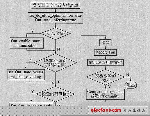
The automatic optimization strategy consists of two stages: reading and compiling.
a) Reading phase: Reading the design described in HDL or state table; automatically detecting the triggers of the state machine; marking the state vector and state encoding characteristics of the state machine.
b) Compilation phase: Re-divide the design hierarchy containing the state machine; extract the state machine from the divided design; determine the coding style; reduce the number of transitions if possible; assign states; generate state assignments for the DC internal data structure based on the logic netlist of the state machine; flatten the newly created design hierarchy; continue with other DC optimization steps.
Figure 2 shows the automatic optimization process, which lists different optional commands that can be selected according to different designs.

Figure 2: Automatic optimization process of finite state machine based on DC Ultra
2.2 Manual optimization strategy based on DC2Expert
When the input design file is not described in HDL, or DC cannot automatically identify the state machine from the HDL file, a manual optimization strategy is used.
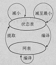
Figure 3 shows the basic flow of the manual optimization strategy, which shows the relationship between the commands used, the state table describing the state machine, and the netlist.

Figure 3 FSM mobile phone optimization command algorithm
As can be seen from Figure 3, manual optimization includes four stages: netlist generation, state table extraction, state table-based optimization, and netlist mapping. The Compile command generates a netlist based on the input HDL file, the Extract command generates a state table based on the netlist, and the Compile command generates a mapped netlist based on the state table optimized by the state machine. The optional commands reduce_fsm and minimize_fsm operate based on the state table. Reduce_fsm attempts to reduce the complexity of the combinational logic associated with the state machine, and minimize_fsm attempts to reduce the number of states.
Manual optimization includes the following steps:
(b) Read the design into DC.
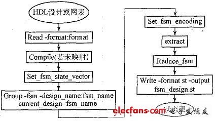
If the design is not given in state table format, extract the state table as follows:
Run compile2map_effort low to get a netlist of input files;
Specify the state vector using set_fsm_state_vector as needed;
Use group2fsm to separate the state machine logic into a separate module and make that module the current design;
Use set_fsm_encoding to assign the state machine state;
Use extract to extract the state machine logic from the design;
Use reduce_fsm as needed to reduce the complexity of the combinational logic associated with the state machine;
Use minimize_fsm as needed to try to reduce the number of states; use minimize_fsm to try to reduce the number of states.
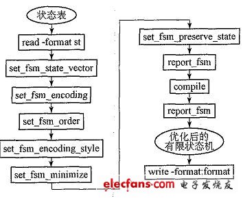
c) Select appropriate commands as needed to modify the properties of the state machine based on the state table, such as state vector, state encoding, encoding style, etc.
d) Specify circuit-level constraints and properties.
e) Compile the entire design.
Figure 4 is the process of extracting the state machine.

FIG5 is an optimization process based on the state table.

3 Issues that should be noted
Not all finite state machines can use the optimization strategies introduced in this article. The original design file should meet the following conditions:
a) All ports should be input or output ports only. Input and output ports are not supported.
b) When there are multiple state machines in a module, only one state machine can be extracted each time the module is compiled, and which state machine is extracted is random, so it is recommended that each module contains only one finite state machine.
c) A state machine can contain only 1 clock.
4 Conclusion
The optimization strategy introduced in this article can effectively improve the performance of the state machine compared to the standard compilation process without changing the source code. However, because the state is re-encoded during the optimization process, especially the manual optimization process, if the new encoding is inconsistent with the original encoding, it will cause logical errors, so other means should be used to perform logic verification when using this strategy.
Previous article:The development and application of 3D laser measurement technology
Next article:Sources of Current Error in Nanoscale Measurements
Recommended ReadingLatest update time:2024-11-16 22:00
- Popular Resources
- Popular amplifiers
- High signal-to-noise ratio MEMS microphone drives artificial intelligence interaction
- Advantages of using a differential-to-single-ended RF amplifier in a transmit signal chain design
- ON Semiconductor CEO Appears at Munich Electronica Show and Launches Treo Platform
- ON Semiconductor Launches Industry-Leading Analog and Mixed-Signal Platform
- Analog Devices ADAQ7767-1 μModule DAQ Solution for Rapid Development of Precision Data Acquisition Systems Now Available at Mouser
- Domestic high-precision, high-speed ADC chips are on the rise
- Microcontrollers that combine Hi-Fi, intelligence and USB multi-channel features – ushering in a new era of digital audio
- Using capacitive PGA, Naxin Micro launches high-precision multi-channel 24/16-bit Δ-Σ ADC
- Fully Differential Amplifier Provides High Voltage, Low Noise Signals for Precision Data Acquisition Signal Chain
- Innolux's intelligent steer-by-wire solution makes cars smarter and safer
- 8051 MCU - Parity Check
- How to efficiently balance the sensitivity of tactile sensing interfaces
- What should I do if the servo motor shakes? What causes the servo motor to shake quickly?
- 【Brushless Motor】Analysis of three-phase BLDC motor and sharing of two popular development boards
- Midea Industrial Technology's subsidiaries Clou Electronics and Hekang New Energy jointly appeared at the Munich Battery Energy Storage Exhibition and Solar Energy Exhibition
- Guoxin Sichen | Application of ferroelectric memory PB85RS2MC in power battery management, with a capacity of 2M
- Analysis of common faults of frequency converter
- In a head-on competition with Qualcomm, what kind of cockpit products has Intel come up with?
- Dalian Rongke's all-vanadium liquid flow battery energy storage equipment industrialization project has entered the sprint stage before production
- Allegro MicroSystems Introduces Advanced Magnetic and Inductive Position Sensing Solutions at Electronica 2024
- Car key in the left hand, liveness detection radar in the right hand, UWB is imperative for cars!
- After a decade of rapid development, domestic CIS has entered the market
- Aegis Dagger Battery + Thor EM-i Super Hybrid, Geely New Energy has thrown out two "king bombs"
- A brief discussion on functional safety - fault, error, and failure
- In the smart car 2.0 cycle, these core industry chains are facing major opportunities!
- The United States and Japan are developing new batteries. CATL faces challenges? How should China's new energy battery industry respond?
- Murata launches high-precision 6-axis inertial sensor for automobiles
- Ford patents pre-charge alarm to help save costs and respond to emergencies
- New real-time microcontroller system from Texas Instruments enables smarter processing in automotive and industrial applications
- Oscilloscope test inductor saturation current and inductance value
- MTK7686 serial port transparent transmission
- 【Silicon Labs Development Kit Review】+Breathing Light Example
- Shouldn't the positive and negative power supplies of the op amp be connected in series to have a reference point?
- The amplifier has a high PSRR, so there is no need to worry about power supply variations?
- How to design the mobile phone power-on circuit
- Request expert explanation
- The output waveform of the Siler oscillator is asymmetrical up and down?
- Python Machine Learning Basics Tutorial
- Can pure software development be transferred to embedded software development?

 A review of learning-based camera and lidar simulation methods for autonomous driving systems
 ICCV2023 Paper Summary: Datasets and Evaluation


 京公网安备 11010802033920号