1 Waveform Generator
1.1 Overview of on-chip waveform generator WFG
The on-chip waveform generator 'WFG' (Wave Form Generator) is one of the unique features of 8XCl96MC/MD. It has three synchronous PWM modules, each module contains a phase comparison register, a dead-time generator and a pair of programmable outputs. The WFG can generate three independent pairs of PWM waveforms, but they have a common carrier frequency, dead-time and operation mode. Once started, the WFG only requires the CP to intervene when changing the PWM duty cycle. The dedicated registers of the waveform generator are the bidirectional counter 'WG-COUNT', the reload register WG-RELOAD, the phase comparison buffer register WG-RCOMPX, the control register WG·C0N, and the output control buffer register WG-OUT. The user can write to the WG-RELOAD register, and its value is periodically (depending on the operation mode) loaded into the second register, which is compared with the WG-COUNT by this counter comparison register. The loading of the second register occurs when WG-COUNT=1 or the value of WG-COUNT is equal to the value of the counter comparison register, which is related to the operation mode of the WFG. If "0" is written to the WG_RELOAD register, when the value is loaded into the counter, it stops counting.
1.2 Basic working principle of waveform generator
The waveform generator is functionally divided into three parts. The time base generator, phase driver channel and control circuit. The time base generator establishes the carrier period for PWM. The period depends on the value and operation mode of the WG-RELOAD register. The core of the time base generator is a 16-bit bidirectional counter WG-COUNT, which can work in 4 different ways to generate center-aligned or edge-aligned PWM. The center-aligned PWM waveform has small harmonics and is usually center-aligned. The phase drive channel determines the duty cycle of the PWM waveform. It has 3 independent phase drive channels, their circuits are the same, and each channel has a pair of programmable outputs. Each phase channel contains a programmable signal-free time generator to prevent a pair of complementary outputs from being valid at the same time. The control part contains some registers used to determine the operating mode and other configuration information. A programmable protection circuit can monitor the EXTINT input pin. If a valid event is detected, an interrupt is generated to disable the waveform output.
The working mode of the time base generator WG-COUNT is 0 and 1. After power-on reset, the value of all registers in WFG is 0. The counter stops working. All values written into WG-REL0AD are valid after 1/2 state cycle (one crystal oscillator cycle). The value written into WG-RELOAD for the first time will be transferred to WG-COUNT. If the count enable bit EC in the WG-CON register is 1, it starts to count down by 1 to 0001H, waits for a state cycle and then counts up by 1 until the value in WG-COUNT is equal to the value of the count comparison register. At this time, a carrier cycle is completed. When the value of the count comparison register is equal to WG-COUNT, the content of WG-RELOAD is loaded into WG-COUNT and the count comparison register; the content of WG-COMPX (X=1, 2, 3) is loaded into the phase comparison register; the content of the output buffer register is loaded into WG-OUT; and the WG interrupt flag is set to 1 in the PI-PEND register. After the original (or new) value is reloaded into WG-COUNT, WG-COUNT starts counting a new switching cycle, and the cycle repeats. 'The relationship between the output data of WG-COUNT and time is a triangle. Carrier cycle Ts = 4 × WG-RELOAD / Fxtal (μs); WG-RELOAD is a 16-bit binary number; Fxta is the crystal frequency on the xtal pin, ignoring the no-signal time; the output "valid" time is ToutpuT = 4 × WG- COMP / Fxtal (μs), where the value of WC-COMP is 16 bits, equal to or less than WG-RELOAD, and the duty cycle = WG-COMP / WG-RELOAD × 100%. It can be seen that changing the value of WG-RELOAD will not only change the carrier cycle of PWM, but also change the duty cycle of PWM. Only by changing WG-RELOAD and changing WG-COMP proportionally at the same time, it is possible to change the carrier cycle without changing the duty cycle.
Both working modes 0 and 1 generate center-aligned PWM. In mode 0, an interrupt request is generated once per carrier cycle, generated at the peak of the counter triangle wave (WG-COUT=WG-RELOAD). At this time, the values of each buffer of the waveform generator will be reloaded into the associated register. Modes 2 and 3 are edge-aligned PWM, and the counter works in the up-counting mode. Its counter waveform is a sawtooth waveform.
2 Principles of controlling stepper motors
2.1 Working Principle of Stepper Motor Control
Stepper motors, also known as pulse motors, are electromechanical actuators that convert electrical pulse signals into corresponding angular displacements or linear displacements. Whenever a pulse is input, the motor rotates an angle and moves forward one step. Therefore, the angular displacement output by the stepper motor is proportional to the number of input pulses, and the corresponding speed is proportional to the pulse frequency. By controlling the number and frequency of input pulses and the power-on sequence of each phase winding of the motor, various required operating characteristics can be obtained. The position and speed of the motor are in a one-to-one correspondence between the number of conduction times (number of pulses) and the frequency. The direction is determined by the conduction sequence. Stepper motors are composed of three major elements: step angle (involving the number of phases), static torque, and current. Once the three major elements are determined, the model of the stepper motor is determined. Stepper motors can be divided into two-phase motors, three-phase motors, four-phase motors, five-phase motors, etc. according to the number of phases. They are widely used in digital control systems.
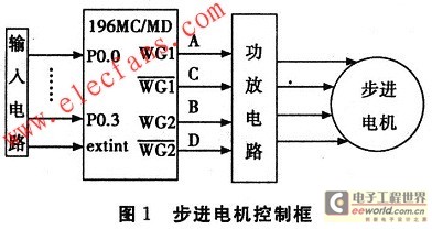
The four-phase stepper motor control circuit is shown in Figure 1. This scheme uses two sets of outputs of the 8XC196MC waveform generator. It consists of an input circuit, a microprocessor, an amplifier circuit, etc. The timing of controlling the driving stepper motor is a half-step timing. One modulation cycle controls eight beats. Its control timing is A-AB-B-BC-C-CD-D-DA-A (forward), DA-D-CD-C-BC-B-BA-A-DA (reverse).

Step angle: Qn=360°/8*number of rotor teeth=360°/8*50=0.9°(number of rotor teeth=50), then the number of steps required for the stepper motor to make one revolution is: 360°/0.9°=400. The rotation of the motor is determined based on the input information.
2.2 Power-frequency control characteristics
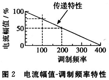
The establishment of the power supply frequency control characteristic (AMP) data table, since the applied signal is a DC signal, it can be considered that the current is proportional to the voltage, and controlling the current is also controlling the voltage. When the modulation frequency is 0, the current amplitude is the largest, and the table data is normalized to 65535 (0FFFFH). When the modulation frequency is 400 Hz, the current amplitude data is 0, and a data is taken every 0.25 Hz. The highest modulation frequency is 200 Hz, so the table contains 801 data items, occupying a total of 1,602 bytes. So WG_COMP=AMP×WB_RELOAD/216. Among them: WG_COMP is the value loaded into the comparison register; AMP is the current amplitude found in the table; WG-RELOAD is the carrier period.


2.3 Block Diagram
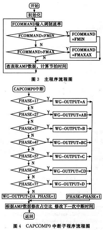
The main program initialization must set to allow CAPCOMP0 (INT02) interrupt, allow EXTINT (INT14) interrupt, set the minimum and maximum modulation frequency, set the initial current amplitude, set the PWM carrier cycle, set the initial PWM duty cycle, open interrupts, etc. The modulation frequency is loaded by the input circuit, the modulation frequency is compared, and the limit of the modulation frequency is controlled within the initial maximum to minimum range. The data in the AMP table is retrieved and the next beat time is calculated. The CAPCOMP0 interrupt subroutine controls the output of the eight-beat rotation characteristics of the motor, and modifies the duty cycle and the next interrupt time at the end of the interrupt program.

3 Conclusion
This article uses single-chip microcomputer technology to control the rotation of the motor, making programming simpler from complex. INTEL's 8XC196MC series is a 16-bit microcontroller designed specifically for high-speed motor control. Its suffix MC is the abbreviation of the English word "Motor Controller" and has been widely used in motor control. It has the characteristics of high performance, full functions, and user-friendly, especially high-speed processing capabilities and special applications for alternating current. Therefore, it will be widely used in my country's intelligent control field and will also bring considerable economic benefits.
Previous article:Design of automatic driving control system for unmanned vehicles
Next article:DS3882 Dual-Channel CCFL Controller
- Popular Resources
- Popular amplifiers
- High signal-to-noise ratio MEMS microphone drives artificial intelligence interaction
- Advantages of using a differential-to-single-ended RF amplifier in a transmit signal chain design
- ON Semiconductor CEO Appears at Munich Electronica Show and Launches Treo Platform
- ON Semiconductor Launches Industry-Leading Analog and Mixed-Signal Platform
- Analog Devices ADAQ7767-1 μModule DAQ Solution for Rapid Development of Precision Data Acquisition Systems Now Available at Mouser
- Domestic high-precision, high-speed ADC chips are on the rise
- Microcontrollers that combine Hi-Fi, intelligence and USB multi-channel features – ushering in a new era of digital audio
- Using capacitive PGA, Naxin Micro launches high-precision multi-channel 24/16-bit Δ-Σ ADC
- Fully Differential Amplifier Provides High Voltage, Low Noise Signals for Precision Data Acquisition Signal Chain
- Innolux's intelligent steer-by-wire solution makes cars smarter and safer
- 8051 MCU - Parity Check
- How to efficiently balance the sensitivity of tactile sensing interfaces
- What should I do if the servo motor shakes? What causes the servo motor to shake quickly?
- 【Brushless Motor】Analysis of three-phase BLDC motor and sharing of two popular development boards
- Midea Industrial Technology's subsidiaries Clou Electronics and Hekang New Energy jointly appeared at the Munich Battery Energy Storage Exhibition and Solar Energy Exhibition
- Guoxin Sichen | Application of ferroelectric memory PB85RS2MC in power battery management, with a capacity of 2M
- Analysis of common faults of frequency converter
- In a head-on competition with Qualcomm, what kind of cockpit products has Intel come up with?
- Dalian Rongke's all-vanadium liquid flow battery energy storage equipment industrialization project has entered the sprint stage before production
- Allegro MicroSystems Introduces Advanced Magnetic and Inductive Position Sensing Solutions at Electronica 2024
- Car key in the left hand, liveness detection radar in the right hand, UWB is imperative for cars!
- After a decade of rapid development, domestic CIS has entered the market
- Aegis Dagger Battery + Thor EM-i Super Hybrid, Geely New Energy has thrown out two "king bombs"
- A brief discussion on functional safety - fault, error, and failure
- In the smart car 2.0 cycle, these core industry chains are facing major opportunities!
- The United States and Japan are developing new batteries. CATL faces challenges? How should China's new energy battery industry respond?
- Murata launches high-precision 6-axis inertial sensor for automobiles
- Ford patents pre-charge alarm to help save costs and respond to emergencies
- New real-time microcontroller system from Texas Instruments enables smarter processing in automotive and industrial applications
- Understand the factors that determine the different performance of ARM core MCUs
- 【Zero Knowledge ESP8266】HTTP WEB Server Example
- Japanese telecom giant counts company trips as business trips and free flights
- Free Download | Keysight Technologies invites you to experience various test software
- The rich flower in the world is so beautiful!
- [ESP32-Audio-Kit Audio Development Board Evaluation] Development Environment Construction and Problems
- How to derive the transfer function of the Debo integrator in 3.2 in circuit design based on operational amplifiers and analog integrated circuits
- 【K210 Series】4. MicroPython is still not perfect
- The Differences Between Leaded and Lead-free PCB Processes
- BMS solutions for electric bicycles and electric motorcycles under the new national standard

 A review of learning-based camera and lidar simulation methods for autonomous driving systems
 Visual ModelQ V7


 京公网安备 11010802033920号