A circuit containing only one independent energy storage element is called a first-order circuit. When there is no excitation in the circuit, the response caused only by the initial energy storage of the energy storage element is called a zero-input response.
1. Zero input response of RC circuit
As shown in Figure 8-4-1, the switch S
is originally in position 1, the circuit has reached a steady state, and the voltage source voltage is
,
then
. At
time , S switches from 1 to 2. The zero input response and are deduced below
.
![]()
![]()
![]()
![]()
![]()

Figure 8-4-1
When
S switches to 2, we
get:
![]()
![]()
![]() (Formula 8-4-1)
(Formula 8-4-1)
Substituting
into the above formula, we get:
![]()
![]() (Formula 8-4-2)
(Formula 8-4-2)
(Equation 8-4-2) is a first-order linear homogeneous differential equation with constant coefficients, and its characteristic equation is:
![]()
The characteristic roots are:
![]()
The general solution to the homogeneous equation is:
![]() (Formula 8-4-3)
(Formula 8-4-3)
The integral constant A in (Formula 8-4-3) is determined by the initial conditions. According to the path replacement rule, we get:
, and substitute it into (Formula 8-4-3), we get:
![]()
![]()
then:
![]() (Formula 8-4-4),
(Formula 8-4-5)
(Formula 8-4-4),
(Formula 8-4-5)
![]()
The negative sign in (Equation 8-4-5) indicates that the actual capacitor discharge current direction is opposite to the assumed reference direction.
It can also be calculated as follows:
![]()
![]()
Figure 8-4-2 plots
the curves of
and
, both of which decay exponentially.
![]()
![]()

Figure 8-4-2
In (Equation 8-4-4) and (Equation 8-4-5), contains
,
which has the dimension of time, and is therefore called the time constant of the circuit. When C
is 1 farad
and R
is 1 ohm
,
it is 1 second
. The size of the time constant
reflects the speed of the transition process.
The larger it is, the longer the transition process lasts and the slower the transition process proceeds;
the smaller it is, the shorter the transition process lasts and the faster the transition process proceeds.
![]()

![]()
![]()

![]()


The following uses the attenuation curve of capacitor voltage
 as an example to introduce the graphical method for finding the time constant
. In Figure 8-4-3, draw a tangent from any point P on the attenuation curve, and its
intersection with the t-axis is
, draw a perpendicular line from point P to the t-axis, and
its intersection with the t-axis is P', then:


The decay curve of or i
is obtained through experiments
and then calculated by graphical method
, which is a useful method in practical work.


Figure 8-4-3
The size of the time constant
depends on the structure and parameters of the circuit and has nothing to do with the excitation.
The time constant of the series circuit
.
The larger
the R
and C
,
the larger the time constant. When R
is constant and C
is larger,
the initial energy stored on
the capacitor C
is larger and the discharge time is longer; when C
is constant and R
is larger, the discharge current is smaller and the discharge time is longer.

![]()
![]()

![]()
2.
Zero input response of the circuit
![]()
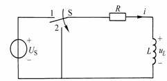
As shown in Figure 8-4-4, the voltage source voltage is
, the switch S
is originally placed in position 1, and the circuit has reached a steady state. At this time, the inductor is equivalent to a short circuit,
. When
, the switch S
switches from 1 to 2. Find the zero input response
,
.
![]()
![]()
![]()
![]()
![]()

Figure 8-4-4
After the switch
is switched to 2, the reference direction is selected as shown in Figure 8-4-4, and the following
is obtained:
![]()
![]()
![]() (Formula 8-4-7)
(Formula 8-4-7)
(Equation 8-4-7) is a first-order linear homogeneous differential equation with constant coefficients, and its characteristic equation is:
![]()
The characteristic roots are:
![]() (Formula 8-4-8)
(Formula 8-4-8)
The general solution to the homogeneous equation is:
![]() (Formula 8-4-9)
(Formula 8-4-9)
The integral constant A in (Equation 8-4-9) is determined by the initial conditions.
According to the switching rule:
![]() (Formula 8-4-10)
(Formula 8-4-10)
From (Formula 8-4-9):
![]()
then:
![]() ,
(Formula 8-4-11)
,
(Formula 8-4-11)
![]()
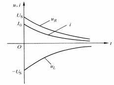
It can be seen that after switching, the current
decays
from the initial value
according to the exponential law and finally decays to zero, as shown in Figure 8-4-5.
![]()
![]()

Figure 8-4-5
Resistor voltage:
![]() (Formula 8-4-12)
(Formula 8-4-12)
Inductor voltage:
![]() (Formula 8-4-13)
(Formula 8-4-13)
![]() ,
differ by a negative sign, and the change patterns of both are the same as that of the current. Their time-varying curves are also shown in Figure 8-4-5.
,
differ by a negative sign, and the change patterns of both are the same as that of the current. Their time-varying curves are also shown in Figure 8-4-5.
![]()
In (Equation 8-4-11) to (Equation 8-4-13), contains
,
has the dimension of time, when R
is 1 ohm
, L
is 1 Henry
, then
is 1 second
,
just like the time constant in the circuit, it reflects the speed of the transition process.
![]()

![]()
![]()

![]()
![]()
Previous article:Zero-state response of a first-order circuit
Next article:How SCSI (Small Computer System Interface) works
- Popular Resources
- Popular amplifiers
- High signal-to-noise ratio MEMS microphone drives artificial intelligence interaction
- Advantages of using a differential-to-single-ended RF amplifier in a transmit signal chain design
- ON Semiconductor CEO Appears at Munich Electronica Show and Launches Treo Platform
- ON Semiconductor Launches Industry-Leading Analog and Mixed-Signal Platform
- Analog Devices ADAQ7767-1 μModule DAQ Solution for Rapid Development of Precision Data Acquisition Systems Now Available at Mouser
- Domestic high-precision, high-speed ADC chips are on the rise
- Microcontrollers that combine Hi-Fi, intelligence and USB multi-channel features – ushering in a new era of digital audio
- Using capacitive PGA, Naxin Micro launches high-precision multi-channel 24/16-bit Δ-Σ ADC
- Fully Differential Amplifier Provides High Voltage, Low Noise Signals for Precision Data Acquisition Signal Chain
- Innolux's intelligent steer-by-wire solution makes cars smarter and safer
- 8051 MCU - Parity Check
- How to efficiently balance the sensitivity of tactile sensing interfaces
- What should I do if the servo motor shakes? What causes the servo motor to shake quickly?
- 【Brushless Motor】Analysis of three-phase BLDC motor and sharing of two popular development boards
- Midea Industrial Technology's subsidiaries Clou Electronics and Hekang New Energy jointly appeared at the Munich Battery Energy Storage Exhibition and Solar Energy Exhibition
- Guoxin Sichen | Application of ferroelectric memory PB85RS2MC in power battery management, with a capacity of 2M
- Analysis of common faults of frequency converter
- In a head-on competition with Qualcomm, what kind of cockpit products has Intel come up with?
- Dalian Rongke's all-vanadium liquid flow battery energy storage equipment industrialization project has entered the sprint stage before production
- Allegro MicroSystems Introduces Advanced Magnetic and Inductive Position Sensing Solutions at Electronica 2024
- Car key in the left hand, liveness detection radar in the right hand, UWB is imperative for cars!
- After a decade of rapid development, domestic CIS has entered the market
- Aegis Dagger Battery + Thor EM-i Super Hybrid, Geely New Energy has thrown out two "king bombs"
- A brief discussion on functional safety - fault, error, and failure
- In the smart car 2.0 cycle, these core industry chains are facing major opportunities!
- The United States and Japan are developing new batteries. CATL faces challenges? How should China's new energy battery industry respond?
- Murata launches high-precision 6-axis inertial sensor for automobiles
- Ford patents pre-charge alarm to help save costs and respond to emergencies
- New real-time microcontroller system from Texas Instruments enables smarter processing in automotive and industrial applications
- Could you please advise what is wrong with this circuit?
- USB power supply and DC power supply issues
- Analysis of the advantages of single chip microcomputer in power supply design application
- Fundamentals of MOSFET and IGBT Gate Driver Circuits
- TI_DSP_SRIO - DirectIO Operations - Basics
- Is it possible to use the same set of programs for zstack router and terminal?
- How to use PNP and NPN transistors
- These are two different power supplies. Can I collect the voltage drop of R0? Get the AD value of the voltage, divide it by the resistance value, and then...
- stm32f103vet6 industrial control board and 485 protocol sensor
- Renesas CPK-RA6M4 Development Board Review ----ADC

 TC52N1837ECTRT


 京公网安备 11010802033920号