When all energy storage elements have no initial energy storage and the circuit is in a zero initial state, the response generated in the circuit by external excitation is called a zero-state response.
The following discusses the zero-state response of the circuit when the excitation is DC and sinusoidal AC
respectively
.
![]()
![]()
1. Zero-state response under DC excitation.
1.
Series circuit
![]()
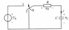
As shown in Figure 8-5-1, switch S
is originally placed in position 2, and the circuit has reached a steady state, that is
, there is no initial energy storage on the capacitor. At
time , switch S
is switched from 2 to 1, and
the circuit is connected to a DC voltage source. Find the zero-state response
,
, and
after the switch
.
![]()
![]()
![]()
![]()
![]()
![]()

Figure 8-5-1
When
the switch S
is switched to 1, we
get:
![]()
![]()
![]() (Formula 8-5-1)
(Formula 8-5-1)
This is a first-order linear non-homogeneous differential equation with constant coefficients. Based on the knowledge of solving differential equations, we can get the special solution:
![]()
General solution to a homogeneous equation:
![]()
The full solution is:
![]()
![]() (Formula 8-5-2)
(Formula 8-5-2)
According to the route switching rules:
![]()
From (Formula 8-5-2):
![]()
therefore:
![]()
Finally, we get:
![]() (Formula 8-5-3)
(Formula 8-5-3)
![]() (Formula 8-5-4)
(Formula 8-5-4)
![]() (Formula 8-5-5)
(Formula 8-5-5)
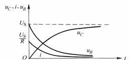
According to (Equation 8-5-3) - (Equation 8-5-5), draw the zero-state response
and
the curve of changing
with
time, as shown in Figure 8-5-2.
![]()
![]()
![]()

Figure 8-5-2
In the circuit shown in Figure 8-5-1, when
, the voltage source charges the capacitor
. The capacitor
gradually increases from the initial voltage of zero and finally charges to the steady-state voltage
, while the current
gradually decreases from the initial value and finally decays to the steady-state value of zero.
![]()
![]()
![]()
2.
Series circuit.
![]()
As shown in Figure 8-5-3, switch S
is placed in position 2, and the circuit has reached a steady state, that is
,
there is no initial energy storage on the inductor L. At
time , switch S
is switched from 2 to 1,
and
the circuit is connected to a DC voltage source
. Find the zero-state response
,
and
after the switching
.
![]()
![]()
![]()
![]()
![]()
![]()
![]()

Figure 8-5-3
After
, switch S
is switched to 1, and we
get:
![]()
![]()
![]() (Formula 8-5-6)
(Formula 8-5-6)
(Equation 8-5-6) is a first-order linear non-homogeneous differential equation with constant coefficients. The full solution of this equation is the sum of the particular solution and the general solution of the homogeneous equation, that is:
![]() (Formula 8-5-7)
(Formula 8-5-7)
![]() represents the complete solution,
represents the special solution, and
represents the general solution. The steady-state current that the circuit reaches a new stable state after switching is the special solution, that is:
represents the complete solution,
represents the special solution, and
represents the general solution. The steady-state current that the circuit reaches a new stable state after switching is the special solution, that is:
![]()
![]()
![]() (Formula 8-5-8)
(Formula 8-5-8)
The general solution is:
![]() (Formula 8-5-9)
(Formula 8-5-9)
So, the full solution is:
![]() (Formula 8-5-10)
(Formula 8-5-10)
The integral constant A in (Equation 8-5-10)
is determined by the initial conditions. At
time , according to the switching rule:
![]()
![]()
From (Formula 8-5-10):
![]()
therefore:
![]()
Finally, we get:
![]() (Formula 8-5-11)
(Formula 8-5-11)
![]() (Formula 8-5-12)
(Formula 8-5-12)
![]() (Formula 8-5-13)
(Formula 8-5-13)
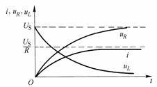
Obviously,
, satisfies
. Figure 8-5-4 plots the zero-state response
,
and
curves.
![]()
![]()
![]()
![]()
![]()

Figure 8-5-4
2. Zero-state response under sinusoidal AC excitation
1.
Series circuit
![]()
Still taking the circuit shown in Figure 8-5-1 as an example, the DC voltage source is changed to a sinusoidal AC voltage source
.
After that,
the differential equation of the circuit is obtained by:
![]()
![]()
![]()
![]() (Formula 8-5-14)
(Formula 8-5-14)
![]() The total solution of is equal to the sum of the particular solution
and the general solution
, that is:
The total solution of is equal to the sum of the particular solution
and the general solution
, that is:
![]()
![]()
![]()
Since the excitation is sinusoidal AC excitation,
it is a steady-state component,
which is a transient component. The steady-state component
can be calculated using phasor:
![]()
![]()
![]()
![]()

Where:
![]()
![]()
![]()
The transient component
is still
, so the full solution is:
![]()
![]()
![]() (Formula 8-5-15)
(Formula 8-5-15)
At
the moment, according to the switching rule
, determine the integral constant:
![]()
![]()
From (Formula 8-5-15):
![]()
![]()
Finally, we get:
![]() (Formula 8-5-16)
(Formula 8-5-16)
![]() (Formula 8-5-17)
(Formula 8-5-17)
![]() (Formula 8-5-18)
(Formula 8-5-18)
(Equation 8-5-16) to (Equation 8-5-18) show that the initial phase angle of the power supply
has an impact on the size of the transient component, usually
called the switch-on angle. When
or
, the transient component of the capacitor voltage is the largest. It is not difficult to see from (Equation 8-5-16) that the maximum value of the capacitor transition voltage will never exceed
twice the amplitude of the steady-state voltage. However, it can be seen from (Equation 8-5-17) that in some cases, the maximum value of the transition current will greatly exceed the amplitude of the steady-state current
.
![]()
![]()
![]()
![]()
![]()
![]()
2. RL series circuit
Still taking the circuit shown in Figure 8-5-3 as an example, the DC voltage source is changed to a sinusoidal AC voltage source
.
After that, the differential equation of the circuit obtained by KVL is:
![]()
![]()
![]() (Formula 8-5-19)
(Formula 8-5-19)
The initial condition is still
. As mentioned before, the total solution of a non-homogeneous differential equation is
the sum of
the particular solution
and the general solution
, that is:
![]()
![]()
![]()
![]()
The right side of (Equation 8-5-19) is a sinusoidal function, and the special solution is also a sinusoidal function. The special solution is the steady-state current under sinusoidal AC excitation, which can be solved using phasor:
![]()

Where:
![]() ,
,
![]()
![]() (Formula 8-5-20)
(Formula 8-5-20)
The transient current is still:
![]() (Formula 8-5-21)
(Formula 8-5-21)
So the full solution is:
![]() (Formula 8-5-22)
(Formula 8-5-22)
According to the route switching rules:
![]()
From (Formula 8-5-22):
![]()
thus:
![]()
Finally, we get:
![]() (Formula 8-5-23)
(Formula 8-5-23)
![]() (Formula 8-5-24)
(Formula 8-5-24)
![]() (Formula 8-5-25)
(Formula 8-5-25)
Previous article:Total Response of First-Order Circuits and the Three-Element Method
Next article:Zero-input response of a first-order circuit
- Popular Resources
- Popular amplifiers
- High signal-to-noise ratio MEMS microphone drives artificial intelligence interaction
- Advantages of using a differential-to-single-ended RF amplifier in a transmit signal chain design
- ON Semiconductor CEO Appears at Munich Electronica Show and Launches Treo Platform
- ON Semiconductor Launches Industry-Leading Analog and Mixed-Signal Platform
- Analog Devices ADAQ7767-1 μModule DAQ Solution for Rapid Development of Precision Data Acquisition Systems Now Available at Mouser
- Domestic high-precision, high-speed ADC chips are on the rise
- Microcontrollers that combine Hi-Fi, intelligence and USB multi-channel features – ushering in a new era of digital audio
- Using capacitive PGA, Naxin Micro launches high-precision multi-channel 24/16-bit Δ-Σ ADC
- Fully Differential Amplifier Provides High Voltage, Low Noise Signals for Precision Data Acquisition Signal Chain
- Innolux's intelligent steer-by-wire solution makes cars smarter and safer
- 8051 MCU - Parity Check
- How to efficiently balance the sensitivity of tactile sensing interfaces
- What should I do if the servo motor shakes? What causes the servo motor to shake quickly?
- 【Brushless Motor】Analysis of three-phase BLDC motor and sharing of two popular development boards
- Midea Industrial Technology's subsidiaries Clou Electronics and Hekang New Energy jointly appeared at the Munich Battery Energy Storage Exhibition and Solar Energy Exhibition
- Guoxin Sichen | Application of ferroelectric memory PB85RS2MC in power battery management, with a capacity of 2M
- Analysis of common faults of frequency converter
- In a head-on competition with Qualcomm, what kind of cockpit products has Intel come up with?
- Dalian Rongke's all-vanadium liquid flow battery energy storage equipment industrialization project has entered the sprint stage before production
- Allegro MicroSystems Introduces Advanced Magnetic and Inductive Position Sensing Solutions at Electronica 2024
- Car key in the left hand, liveness detection radar in the right hand, UWB is imperative for cars!
- After a decade of rapid development, domestic CIS has entered the market
- Aegis Dagger Battery + Thor EM-i Super Hybrid, Geely New Energy has thrown out two "king bombs"
- A brief discussion on functional safety - fault, error, and failure
- In the smart car 2.0 cycle, these core industry chains are facing major opportunities!
- The United States and Japan are developing new batteries. CATL faces challenges? How should China's new energy battery industry respond?
- Murata launches high-precision 6-axis inertial sensor for automobiles
- Ford patents pre-charge alarm to help save costs and respond to emergencies
- New real-time microcontroller system from Texas Instruments enables smarter processing in automotive and industrial applications
- Smart LED Octahedron
- [Lazy self-care fish tank control system] BLE_MESH fish tank light peripheral production
- Verilog001
- Inter-core Communication Method of TMS320C6678 Multi-core DSP
- How to implement the logic of GD32E230 OAT? Is there any relevant code information?
- Microelectronic Circuit Design (4th Edition, English)
- MAX202 RS-232 Interface Counterfeit Device Warning
- RC π type filter resistor and capacitor value -------
- About the role of capacitors in suppressing differential mode interference and common mode interference
- [Raspberry Pi Pico Review] WS2812B full-color LED light strip/ring display driver

 EL5111IWTZ-T7


 京公网安备 11010802033920号