| TIM_OCMode | Library Description | explain |
| TIM_OCMode_Timing | TIM Output Compare Time Mode | Freeze, output compare not working |
| TIM_OOCMode_Active | TIM output compare active mode | When a comparison occurs, the output is forced high |
| TIM_OCMode_Inactive | TIM output comparison inactive mode | When a comparison occurs, the output is forced low |
| TIM_OCMode_Toggle | TIM output compare trigger mode | When a comparison occurs, the output flips |
| TIM_OCMode_PWM1 | TIM PWM Mode 1 | PWM1 |
| TIM_OCMode_PWM2 | TIM PWM Mode 2 | PWM2 |
/****************************************************************
Function: OC_GPIO_Init
Description: Timer output comparison pin initialization
Input: none
return: none
**********************************************************/
static void OCTiming_GPIO_Init(void)
{
GPIO_InitTypeDef GPIO_InitStructure;
RCC_APB2PeriphClockCmd(RCC_APB2Periph_GPIOC, ENABLE); //Turn on GPIOA clock
GPIO_InitStructure.GPIO_Pin = GPIO_Pin_6 | GPIO_Pin_7 | GPIO_Pin_8 | GPIO_Pin_9;
GPIO_InitStructure.GPIO_Mode = GPIO_Mode_Out_PP;
GPIO_InitStructure.GPIO_Speed = GPIO_Speed_50MHz;
GPIO_Init(GPIOC, &GPIO_InitStructure);
}
/****************************************************************
Function: OC_TIM2_Init
Description: Set the 4 output comparisons of timer 2
Input: none
return: none
**************************************************************/
static void OCTiming_TIM2_Init(void)
{
TIM_TimeBaseInitTypeDef TIM_TimeBaseStructure;
TIM_OCInitTypeDef TIM_OCInitStructure;
RCC_APB1PeriphClockCmd(RCC_APB1Periph_TIM2, ENABLE);
TIM_TimeBaseStructure.TIM_Period = 65535;//Timing period value
TIM_TimeBaseStructure.TIM_Prescaler = 0;//No pre-division
TIM_TimeBaseStructure.TIM_ClockDivision = 0;//Clock is not divided
TIM_TimeBaseStructure.TIM_CounterMode = TIM_CounterMode_Up; //Increase count
TIM_TimeBaseInit(TIM2, &TIM_TimeBaseStructure); //Initialize timer
/* -------------------------------------------------------
Timer configuration output comparison time mode:
the clock frequency of the timer is 72M.
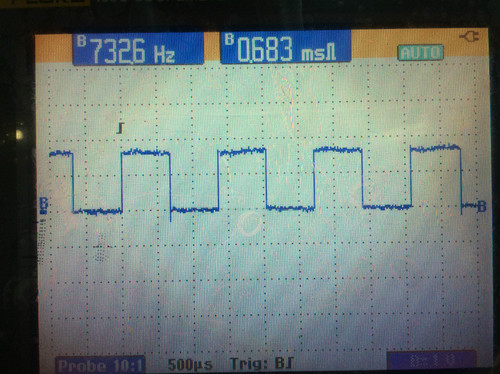
The frequency of PC6 output is 72M/CCR1_Val/2=732Hz, and the duty cycle is 50%.
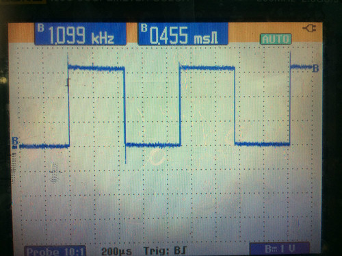
The frequency of PC7 output is 72M/CCR2_Val/2=1099Hz, and the duty cycle is 50%.
The frequency of PC8 output is 72M/CCR3_Val/2=2197Hz, and the duty cycle is 50%.
The frequency of PC9 output is 72M/CCR4_Val/2=4395Hz, and the duty cycle is 50%.
---------------------------------------------------------*/
TIM_OCInitStructure.TIM_OCMode = TIM_OCMode_Timing; //Output comparison time mode
TIM_OCInitStructure.TIM_OutputState = TIM_OutputState_Enable; //Output enable
TIM_OCInitStructure.TIM_Pulse = CCR1_Val; //Set comparison value
TIM_OCInitStructure.TIM_OCPolarity = TIM_OCPolarity_High; //When the timer count value is less than CCR1_Val, it is high level
TIM_OC1Init(TIM2, &TIM_OCInitStructure); //Initialize TIM2 output comparison channel 11
TIM_OC1PreloadConfig(TIM2, TIM_OCPreload_Disable); //Do not automatically re-transfer count value
TIM_OCInitStructure.TIM_OutputState = TIM_OutputState_Enable; //Output enable
TIM_OCInitStructure.TIM_Pulse = CCR2_Val; //Set comparison valueTIM_OC2Init
(TIM2, &TIM_OCInitStructure); //Initialize output comparison channel 2 of TIM2
TIM_OC2PreloadConfig(TIM2, TIM_OCPreload_Disable); //Do not automatically re-transfer count
valueTIM_OCInitStructure.TIM_OutputState = TIM_OutputState_Enable; //Output enableTIM_OCInitStructure.TIM_Pulse
= CCR3_Val; //Set comparison valueTIM_OC3Init
(TIM2, &TIM_OCInitStructure); //Initialize output comparison channel 3 of TIM2
TIM_OC3PreloadConfig(TIM2, TIM_OCPreload_Disable); //Do not automatically re-transfer count valueTIM_OCInitStructure.TIM_OutputState
= TIM_OutputState_Enable; // output enable
TIM_OCInitStructure.TIM_Pulse = CCR4_Val; // set comparison value
TIM_OC4Init(TIM2, &TIM_OCInitStructure); // initialize TIM2 output comparison channel 3
TIM_OC4PreloadConfig(TIM2, TIM_OCPreload_Disable); // do not automatically re-transfer count value
TIM_ITConfig(TIM2, TIM_IT_CC1 | TIM_IT_CC2 | TIM_IT_CC3 | TIM_IT_CC4, ENABLE); // clear interrupt flag
TIM_Cmd(TIM2, ENABLE); // turn on timer
}
/****************************************************************
Function: OC_Int_Config
Description: Timer output compare interrupt configuration
Input: none
return: none
**********************************************************/
static void OCTiming_Int_Config(void)
{
NVIC_InitTypeDef NVIC_InitStructure;
NVIC_InitStructure.NVIC_IRQChannel = TIM2_IRQn; //TIM2 interrupt
NVIC_InitStructure.NVIC_IRQChannelSubPriority = 1; //Priority is 1
NVIC_InitStructure.NVIC_IRQChannelCmd = ENABLE;
NVIC_Init(&NVIC_InitStructure);
}
/****************************************************************
Function: OC_Init
Description: Timer output comparison initialization
Input: none
return: none
**********************************************************/
void OCTiming_Init(void)
{
OCTiming_GPIO_Init(); //Output comparison pin configuration
OCTiming_TIM2_Init(); //Timer 2 output comparison initialization
OCTiming_Int_Config(); //Output comparison interrupt configuration
}
#ifndef __TIMEBASE_H__
#define __TIMEBASE_H__
#include "stm32f10x.h"
#define CCR1_Val 49152
#define CCR2_Val 32768
#define CCR3_Val 16384
#define CCR4_Val 8192
void OCTiming_Init(void);
#endif
/****************************************************************
Function: TIM2_IRQHandler
Description: Timer 2 interrupt service routine
Input: none
return: none
*************************************************************/
void TIM2_IRQHandler(void)
{
static u16 capture = 0;
if (TIM_GetITStatus(TIM2, TIM_IT_CC1) != RESET)//Output comparison channel 1
{
TIM_ClearITPendingBit(TIM2, TIM_IT_CC1);
GPIO_WriteBit(GPIOC, GPIO_Pin_6, (BitAction)(1 - GPIO_ReadOutputDataBit(GPIOC, GPIO_Pin_6)));//Flip level value, generate PWM wave with frequency of 72M/CCR1_Val/2 and duty cycle of 50%
capture = TIM_GetCapture1(TIM2);//Get comparison value
TIM_SetCompare1(TIM2, capture + CCR1_Val);//Reset comparison value
}
if (TIM_GetITStatus(TIM2, TIM_IT_CC2) != RESET)//Output comparison channel 1
{
TIM_ClearITPendingBit(TIM2, TIM_IT_CC2);
GPIO_WriteBit(GPIOC, GPIO_Pin_7, (BitAction)(1 - GPIO_ReadOutputDataBit(GPIOC, GPIO_Pin_7)));//Flip level value, generate PWM wave with frequency of 72M/CCR2_Val/2 and duty cycle of 50%
capture = TIM_GetCapture2(TIM2);//Get comparison value
TIM_SetCompare2(TIM2, capture + CCR2_Val);//Reset comparison value
}
if (TIM_GetITStatus(TIM2, TIM_IT_CC3) != RESET)//Output comparison channel 1
{
TIM_ClearITPendingBit(TIM2, TIM_IT_CC3);
GPIO_WriteBit(GPIOC, GPIO_Pin_8, (BitAction)(1 - GPIO_ReadOutputDataBit(GPIOC, GPIO_Pin_8)));//Flip the level value to generate a PWM wave with a frequency of 72M/CCR3_Val/2 and a duty cycle of 50%
capture = TIM_GetCapture3(TIM2);//Get comparison value
TIM_SetCompare3(TIM2, capture + CCR3_Val);//Reset comparison value
}
if (TIM_GetITStatus(TIM2, TIM_IT_CC4) != RESET)//Output comparison channel 1
{
TIM_ClearITPendingBit(TIM2, TIM_IT_CC4);
GPIO_WriteBit(GPIOC, GPIO_Pin_9, (BitAction)(1 - GPIO_ReadOutputDataBit(GPIOC, GPIO_Pin_9))); //Flip the level value to generate a PWM wave with a frequency of 72M/CCR4_Val/2 and a duty cycle of 50%
capture = TIM_GetCapture4(TIM2); //Get the comparison value
TIM_SetCompare4(TIM2, capture + CCR4_Val); //Reset the comparison value
}
}
/****************************************************************
Function: main
Description: main entry
Input: none
return: none
*************************************************************/
int main(void)
{
BSP_Init();
OCTiming_Init(); //Output comparison initialization
PRINTF("\nmain() is running!\r\n");
while(1)
{
LED1_Toggle();
Delay_ms(1000);
}
}


Previous article:STM32 timer output compare active mode
Next article:STM32 generates 7 PWM waves
Recommended ReadingLatest update time:2024-11-15 14:07


- Popular Resources
- Popular amplifiers
- Learn ARM development(16)
- Learn ARM development(17)
- Learn ARM development(18)
- Embedded system debugging simulation tool
- A small question that has been bothering me recently has finally been solved~~
- Learn ARM development (1)
- Learn ARM development (2)
- Learn ARM development (4)
- Learn ARM development (6)
 Professor at Beihang University, dedicated to promoting microcontrollers and embedded systems for over 20 years.
- LED chemical incompatibility test to see which chemicals LEDs can be used with
- Application of ARM9 hardware coprocessor on WinCE embedded motherboard
- What are the key points for selecting rotor flowmeter?
- LM317 high power charger circuit
- A brief analysis of Embest's application and development of embedded medical devices
- Single-phase RC protection circuit
- stm32 PVD programmable voltage monitor
- Introduction and measurement of edge trigger and level trigger of 51 single chip microcomputer
- Improved design of Linux system software shell protection technology
- What to do if the ABB robot protection device stops
- Do you know all the various motors commonly used in automotive electronics?
- What are the functions of the Internet of Vehicles? What are the uses and benefits of the Internet of Vehicles?
- Power Inverter - A critical safety system for electric vehicles
- Analysis of the information security mechanism of AUTOSAR, the automotive embedded software framework
- Brief Analysis of Automotive Ethernet Test Content and Test Methods
- How haptic technology can enhance driving safety
- Let’s talk about the “Three Musketeers” of radar in autonomous driving
- Why software-defined vehicles transform cars from tools into living spaces
- How Lucid is overtaking Tesla with smaller motors
- Wi-Fi 8 specification is on the way: 2.4/5/6GHz triple-band operation
- STM32F10x stepper motor encoder position control CANWeb source program
- MSP430F249_TimerA timer
- Synthesizable Verilog Syntax (Cambridge University, photocopy)
- [RVB2601 Creative Application Development] Short recording, playback and printing of recording data
- When the carrier data reaches the receiving end, how does the receiving end identify this information?
- SparkRoad Review (7) - FPGA Serial Port Test
- Disable AD auto-start JLink
- Seeking guidance - stc microcontroller remote upgrade program
- Problems with creating sheet symbols for multi-page schematics
- Zigbee Z-Stack 3.0.1 Modify channels using broadcasting

 usb_host_device_code
 Transplantation of real-time operating system RT-ThreadSmart on STM32MP1


 京公网安备 11010802033920号