/****************************************************************
Function: OCActive_GPIO_Init
Description: Output compare active mode timer channel pin configuration
Input: none
return: none
**************************************************************/
static void OCActive_GPIO_Init(void)
{
GPIO_InitTypeDef GPIO_InitStructure;
RCC_APB2PeriphClockCmd(RCC_APB2Periph_GPIOA, ENABLE);
GPIO_InitStructure.GPIO_Pin = GPIO_Pin_0 | GPIO_Pin_1 | GPIO_Pin_2 | GPIO_Pin_3;
GPIO_InitStructure.GPIO_Mode = GPIO_Mode_AF_PP; //Timer channel pins are configured as multiplexed push-pull output
GPIO_InitStructure.GPIO_Speed = GPIO_Speed_50MHz;
GPIO_Init(GPIOA, &GPIO_InitStructure);
}
u16 CCR1_Val = 10000;
u16 CCR2_Val = 5000;
u16 CCR3_Val = 2500;
u16 CCR4_Val = 1250;
/****************************************************************
Function: OCActive_TIM2_Init
Description: Timer 2 is configured to output compare active mode
Input: none
return: none
**************************************************************/
static void OCActive_TIM2_Init(void)
{
TIM_TimeBaseInitTypeDef TIM_TimeBaseStructure;
TIM_OCInitTypeDef TIM_OCInitStructure;
RCC_APB1PeriphClockCmd(RCC_APB1Periph_TIM2, ENABLE); //Initialize TIM2 clock
/* -------------------------------------------------------
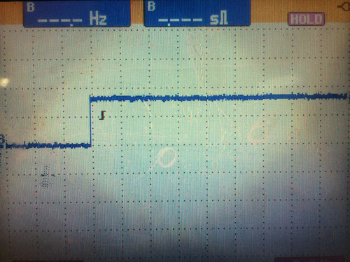
The timer's beat is 720000000/36000/2=1kHz,
TIM_OCMode_Active mode forces the output to be high, and
each channel pin is originally at a low level. After the following delay, it jumps to a high level
TIM2_CH1 delay = CCR1_Val/1kHz = 10s
TIM2_CH2 delay = CCR2_Val/1kHz = 5s
TIM2_CH3 delay = CCR3_Val/1kHz = 2.5s
TIM2_CH4 delay = CCR4_Val/1kHz = 1.25s
---------------------------------------------------------*/
TIM_TimeBaseStructure.TIM_Period = 60000; //Timer counting period
TIM_TimeBaseStructure.TIM_Prescaler = 36000 - 1; //Prescaler
TIM_TimeBaseStructure.TIM_ClockDivision = 2 - 1; //Clock 2 division
TIM_TimeBaseStructure.TIM_CounterMode = TIM_CounterMode_Up; //Increase count
TIM_TimeBaseInit(TIM2, &TIM_TimeBaseStructure); //Initialize timer
TIM_OCInitStructure.TIM_OCMode = TIM_OCMode_Active;//Output comparison active modeTIM_OCInitStructure.TIM_OutputState
= TIM_OutputState_Enable;//Output enableTIM_OCInitStructure.TIM_Pulse
= CCR1_Val;//Set comparison value (jump value)
TIM_OCInitStructure.TIM_OCPolarity = TIM_OCPolarity_High;//The effective level is high
levelTIM_OC1Init(TIM2, &TIM_OCInitStructure);//Initialize output compare registerTIM_OC1PreloadConfig
(TIM2, TIM_OCPreload_Disable);//Turn off preloadTIM_OCInitStructure.TIM_OutputState
= TIM_OutputState_Enable;//Output enableTIM_OCInitStructure.TIM_Pulse
= CCR2_Val;//Set comparison value (jump value)
TIM_OC2Init(TIM2, &TIM_OCInitStructure);//Initialize output compare register
TIM_OC2PreloadConfig(TIM2, TIM_OCPreload_Disable);
TIM_OCInitStructure.TIM_OutputState = TIM_OutputState_Enable;//Output enable
TIM_OCInitStructure.TIM_Pulse = CCR3_Val;//Set comparison value (jump value)
TIM_OC3Init(TIM2, &TIM_OCInitStructure);//Initialize output compare register
TIM_OC3PreloadConfig(TIM2, TIM_OCPreload_Disable);
TIM_OCInitStructure.TIM_OutputState = TIM_OutputState_Enable;//Output enable
TIM_OCInitStructure.TIM_Pulse = CCR4_Val;//Set comparison value (jump value)
TIM_OC4Init(TIM2, &TIM_OCInitStructure); //Initialize output compare register
TIM_OC4PreloadConfig(TIM2, TIM_OCPreload_Disable);
TIM_ARRPreloadConfig(TIM2, ENABLE); //Turn on the automatic reload function of timer 2
TIM_Cmd(TIM2, ENABLE); //Turn on timer 2
}
/****************************************************************
Function: OCActive_Init
Description: Output compare active M mode initialization
Input: none
return: none
*************************************************************/
void OCActive_Init(void)
{
OCActive_GPIO_Init();
OCActive_TIM2_Init();
}
#ifndef __OCACTIVE_H__
#define __OCACTIVE_H__
#include "stm32f10x.h"
void OCActive_Init(void);
#endif
/****************************************************** ************
Function: main
Description: mainInput
: none
return: none
************************* **********************************/
int main(void)
{
BSP_Init();
OCActive_Init() ;
PRINTF("\nmain() is running!\r\n");
while(1)
{
LED1_Toggle();
Delay_ms(1000);
}
}

Previous article:STM32 timer output compare non-active mode
Next article:STM32 timer output comparison time mode
- Popular Resources
- Popular amplifiers
- Learn ARM development(16)
- Learn ARM development(17)
- Learn ARM development(18)
- Embedded system debugging simulation tool
- A small question that has been bothering me recently has finally been solved~~
- Learn ARM development (1)
- Learn ARM development (2)
- Learn ARM development (4)
- Learn ARM development (6)
 Professor at Beihang University, dedicated to promoting microcontrollers and embedded systems for over 20 years.
- LED chemical incompatibility test to see which chemicals LEDs can be used with
- Application of ARM9 hardware coprocessor on WinCE embedded motherboard
- What are the key points for selecting rotor flowmeter?
- LM317 high power charger circuit
- A brief analysis of Embest's application and development of embedded medical devices
- Single-phase RC protection circuit
- stm32 PVD programmable voltage monitor
- Introduction and measurement of edge trigger and level trigger of 51 single chip microcomputer
- Improved design of Linux system software shell protection technology
- What to do if the ABB robot protection device stops
- Wiring harness durability test and contact voltage drop test method
- From probes to power supplies, Tektronix is leading the way in comprehensive innovation in power electronics testing
- From probes to power supplies, Tektronix is leading the way in comprehensive innovation in power electronics testing
- Sn-doped CuO nanostructure-based ethanol gas sensor for real-time drunk driving detection in vehicles
- Design considerations for automotive battery wiring harness
- Do you know all the various motors commonly used in automotive electronics?
- What are the functions of the Internet of Vehicles? What are the uses and benefits of the Internet of Vehicles?
- Power Inverter - A critical safety system for electric vehicles
- Analysis of the information security mechanism of AUTOSAR, the automotive embedded software framework
- Brief Analysis of Automotive Ethernet Test Content and Test Methods
- [Help] spx3819-3.3 regulated output
- Is it a voltage comparator or an oscillator circuit?
- Problems with the full-bridge circuit formed by dual MOS tube Si4288
- Radio frequency allocation map
- [National Technology N32 MCU Development Data]--Full Series Product Selection Table
- CH340G cannot download
- Super detailed! Help you understand the internal structure of the switching power supply chip
- Use VSCode to compile and debug BlueNRG-1 code
- 【AT32WB415 Review】05 RTC Test + Adding Electronic Clock Interface
- Summary of bare metal program burning method for embedded Linux development board

 LM208HB


 京公网安备 11010802033920号