1 Memory Part Principle


Keywords:ARM7
Reference address:Design of soft interrupt program based on ARM7
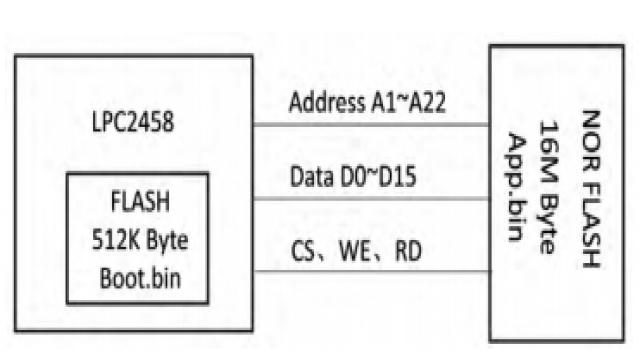
The author used LPC2458 when designing a project. This CPU is an ARM7 core with 512K bytes of on-chip FLASH, 98k bytes of on-chip RAM, supports off-chip LOCAL BUS, and can start the CPU from off-chip NOR FLASH. Due to the large amount of code, the program is placed in the off-chip NOR FLASH. And there is a need to erase and write the off-chip NOR FLASH when running the program. Figure 1 is a block diagram of the storage part.

Figure 1 Schematic diagram of the storage part
In the design, the size of the off-chip NOR FLASH is 16M bytes. 2M of it is planned to store the running program, and the remaining space is used for product operation logs and warning light storage space. Therefore, there is a need to erase and write the off-chip NOR FLASH when the program is running. If the program is erasing the FLASH in the off-chip FLASH that is running normally, there will be a bus conflict problem and this function cannot be implemented. We use the SWI soft interrupt function of the ARM7 core to achieve this.
2 ARM soft interrupt principle (SWI)
There is no official definition of soft interrupt (SWI) so far. I try to define it in comparison with hard interrupt as follows:
1. The time when a soft interrupt occurs is controlled by the program, while the time when a hard interrupt occurs is random.
2. Soft interrupts are caused by program calls, while hard interrupts are triggered by peripherals.
3. The hard interrupt handler must ensure that it can complete its task quickly so that the program will not wait for a long time when executing.
To call a software interrupt in a C program, you need to use the compiler's extended function and use the keyword "_SWI" to declare the interrupt function. Note that the soft interrupt number is also specified when defining the function.
_swi(0x24) void my_swi(void);
In this way, when the function my_swi is called, "SWI 0X24" will be used instead of the normal function call "BL my_swi".
It can be found that software interrupts also have the problem of interrupt branching, that is, different handlers need to be called according to the interrupt number. The soft interrupt number only exists in the SWI instruction code, so it is necessary to read the instruction code that triggers the interrupt in the interrupt handler, and then extract the interrupt number information for further processing. The following is the encoding format of the soft interrupt instruction:
The SWI instruction encoding format in ARM state is 32 bits long, of which 24 bits are the interrupt number.
The SWI instruction encoding format in Thumb state is 16 bits long, of which the lower 8 bits are the interrupt number.
In order to get the address of the SWI instruction in the interrupt handler, the LR register can be used. Every time a SWI is responded, the processor will automatically save and adjust the LR register so that the content inside points to the address of the next instruction of the SWI. Therefore, the interval required to trace the address content in the LR up one instruction is different. If the SWI is executed in ARM state before entering, LR-4 is needed to obtain the SWI instruction address. If it is entered in Thumb state, only LR-2 is needed.
Here is a routine to extract the SWI interrupt number:
MRS R0, SPSR; check the status before entering SWI response
TST R0,#T_bit;
LDRNEH R0, [LR, #-2]; is Thumb, read back the SWI instruction code
BICNE R0, R0, #0xff00; extract the lower 8 bits
LDREQ R0, [LR, #-4]; is ARM, read back the SWI instruction code
BICEQ R0, #ff000000; extract the lower 24 bits;
The content in register R0 is the correct soft interrupt number.
3 Introduction to FLASH CFI Interface
During programming, the software needs to support different models of FLASH from multiple manufacturers, so we use the CFI interface when erasing and writing FLASH.
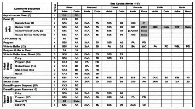
CFI (Common Flash Interface) is an interface developed by JEDEC to help programs read the manufacturer ID and device ID of FLASH, determine the size of FLASH, and obtain various physical characteristics of FLASH, such as the erase time of BLOCK, etc. The main function is to make software and hardware upgrades more convenient, improve hardware compatibility between different manufacturers, and achieve interchangeability of underlying hardware. The FLASH command definition list used in the project is shown in Table 1.

Table 1 NOR FLASH command definition list
4 Implementation plan
4.1 SWI interface implementation program
As shown in Figure 1, the internal FLASH of LPC2458 stores the boot program, and the external FLASH stores the application program. When the external FLASH needs to be erased, a soft interrupt is generated by the application program, causing the program to jump to the internal FLASH for execution. The CPU no longer fetches instructions from the external FLASH, so the external FLASH can be erased. When the soft interrupt program is finished running, the program jumps back to the external FLASH.
Since it is troublesome to transmit parameters in SWI soft interrupt, our SWI soft interrupt program only returns the address of the processing function. After obtaining the address, we redefine it as a function address pointer to simplify the processing and enhance the readability and maintainability of the program.
We take the FLASH write function as an example to illustrate the process of using the SWI method.
//Define the function pointer type
typedef unsigned long (*FuncWR_t)(unsigned long, void *, unsigned long);
//Define the FLASH write function and call the soft interrupt
unsigned long Write_Flash(unsigned long StartAddr, unsigned short* DataPtr, unsigned long Count)
{
Extern unsigned long __swi(3) Get_Write_Addr(void);
FuncWR_t Func; //define a function pointer
Func = (FuncWR_t)Get_Write_Addr();
return Func(StartAddr, DataPtr, Count);
}
unsigned long __swi(3)Get_Write_Addr(void);
unsigned long __swi_3(void) //Get Write Flash Function Address
{
return (unsigned long)NorFlash_Write;
}
NorFlash_Write function interface is defined as follows:
unsigned long NorFlash_Write(unsigned long StartAddr, unsigned short * DataPtr, unsigned long Count);
4.2 CFI interface implementation
There are many source codes for programming using the CFI interface in FLASH on the Internet, so this article will not go into detail. Taking writing FLASH as an example, the function is as follows:
unsigned long NorFlash_Write(unsigned long StartAddr, unsigned short * DataPtr, unsigned long Count)
{
……..
……..
WRITE_CMD(0X5555,0XAAAA);
WRITE_CMD(0X2AAA,0X5555);
WRITE_CMD(0X5555,0XA0A0);
……..
……..
}
5 Conclusion
This article uses the ARM7 core LPC2458 MCU to implement the write operation routine of the FLASH while running the program by using the soft interrupt method. The design method of the ARM7 core MCU soft interrupt program is described in detail. It is hoped that it can serve as a reference for the implementation of soft interrupt programs for MCUs using the ARM7 core and Cortex-M3/M4 core.
Previous article:Software and hardware design of air transmission protocol for contactless CPU card
Next article:Design of network communication circuit for STM32F107
- Popular Resources
- Popular amplifiers
Recommended Content
Latest Microcontroller Articles
- Learn ARM development(16)
- Learn ARM development(17)
- Learn ARM development(18)
- Embedded system debugging simulation tool
- A small question that has been bothering me recently has finally been solved~~
- Learn ARM development (1)
- Learn ARM development (2)
- Learn ARM development (4)
- Learn ARM development (6)
He Limin Column
Microcontroller and Embedded Systems Bible
 Professor at Beihang University, dedicated to promoting microcontrollers and embedded systems for over 20 years.
MoreSelected Circuit Diagrams
MorePopular Articles
- LED chemical incompatibility test to see which chemicals LEDs can be used with
- Application of ARM9 hardware coprocessor on WinCE embedded motherboard
- What are the key points for selecting rotor flowmeter?
- LM317 high power charger circuit
- A brief analysis of Embest's application and development of embedded medical devices
- Single-phase RC protection circuit
- stm32 PVD programmable voltage monitor
- Introduction and measurement of edge trigger and level trigger of 51 single chip microcomputer
- Improved design of Linux system software shell protection technology
- What to do if the ABB robot protection device stops
MoreDaily News
- Analysis of the application of several common contact parts in high-voltage connectors of new energy vehicles
- Wiring harness durability test and contact voltage drop test method
- From probes to power supplies, Tektronix is leading the way in comprehensive innovation in power electronics testing
- From probes to power supplies, Tektronix is leading the way in comprehensive innovation in power electronics testing
- Sn-doped CuO nanostructure-based ethanol gas sensor for real-time drunk driving detection in vehicles
- Design considerations for automotive battery wiring harness
- Do you know all the various motors commonly used in automotive electronics?
- What are the functions of the Internet of Vehicles? What are the uses and benefits of the Internet of Vehicles?
- Power Inverter - A critical safety system for electric vehicles
- Analysis of the information security mechanism of AUTOSAR, the automotive embedded software framework
Guess you like
- DSP Learning (1) Introduction to Digital Signal Processors (DSPs)
- 【Portable Environmental Status Detector】RTC Electronic Clock
- Espressif's ESP32-C3 is an extremely low-power SoC equipped with a RISC-V 32-bit single-core processor
- [Gizwits Gokit3 Review] + AirLink configuration (Arduino)
- Node voltage calculation
- Showing goods + artificial intelligence first board dog bone AI
- [TI mmWave Radar Evaluation]_5_AWR1843BOOST Corridor Ranging Corner Reflector Test
- Operational amplifiers in series can achieve high precision and high output power at the same time
- CC2640 BLE Bluetooth wireless module low power consumption
- pyESP32 board design draft and BOM list

 EL5223CL


 京公网安备 11010802033920号