As fossil energy is decreasing and the problem of global warming caused by excessive greenhouse gas emissions is becoming more and more important, people are actively developing various types of renewable energy on the one hand, and advocating green environmental protection technologies for energy conservation and emission reduction on the other. As an inexhaustible clean energy, solar energy has become an important representative of many renewable energy sources; and in the field of lighting, LED solid-state lighting with long life, energy saving, safety, green environmental protection, rich colors and miniaturization has also been recognized as an important way to save energy and protect the environment in the world. Solar-LED street lights integrate the advantages of both, using clean energy and high-efficiency LEDs to achieve green lighting.
The solar-LED street light solution introduced in this article can automatically detect ambient light to control the working status of the street light, ensure the maximum solar panel efficiency through maximum power point tracking (MPPT), control the LED with constant current, and has battery status output and user-settable LED working time.
System structure and implementation principle
At present, street lamps generally use a high-pressure sodium lamp structure powered by mains electricity. The electronic drive part of the high-pressure sodium lamp needs to convert the mains electricity from AC to DC, and then invert it to AC to drive, resulting in low system efficiency; and because of the use of mains electricity, it is necessary to lay complex and expensive pipelines. Solar-LED street lights do not have the above problems. Since solar panels output DC power and LEDs are also DC-driven light sources, the combination of the two can improve the efficiency of the entire system; the use of solar energy also eliminates the cost of laying cables and related projects.

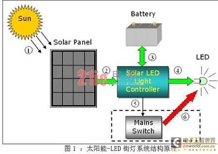
Figure 1 is a schematic diagram of the structure of a solar-LED street light. When the solar panel is exposed to sunlight, its internal PN junction will form new electron-hole pairs, which can generate DC current in a loop; this current flows into the controller and charges the battery in some way. The battery will be charged during the day and provide energy to the LED at night. The operation of the LED is carried out by the controller. While ensuring the constant current operation of the LED, the controller will also monitor the status of the LED and control the working time. In the case of continuous rainy days and insufficient battery power, the controller will send a control signal to start the external mains power supply system (not included in the controller) to ensure the normal operation of the LED. The external mains power supply system is only used as a backup energy source and will only be used when the battery power is insufficient. The battery is charged entirely by solar energy to ensure the maximum use of solar energy.

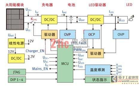
Figure 2: Controller block diagram
Figure 2 is a block diagram of the controller. After the solar panel comes in, it will first pass through a switch MOS tube KCHG to connect to the DC/DC converter (battery charging circuit), and the output of this converter is connected to both ends of the battery (in the actual circuit, it will first pass through a fuse and then connect to the battery). Adding KCHG has two functions: one is to prevent the reverse charging current from the battery when the solar cell output is low; the other is to protect the circuit when the polarity of the solar panel is reversed. The DC/DC converter adopts a buck topology. The selection of the topology must not only consider the maximum power point voltage of the solar panel and the maximum voltage of the battery, but also take into account efficiency and cost. The battery and the LED are also connected through a DC/DC converter (LED drive circuit). Constant current control should be adopted for the LED. Considering the fluctuation range of the battery voltage and the operating voltage range of the LED, the flyback topology is used in the design circuit to ensure constant current output. The efficiency of the flyback topology is generally not as high as that of a simple boost or buck circuit. If you want to improve the efficiency of the system, you can use a boost or buck circuit by optimizing the relationship between the battery voltage and the LED voltage to improve efficiency and possibly further reduce costs.
The control of the entire controller is realized by an MCU. The main tasks of the MCU include the following: first, the MPPT algorithm is used to optimize the efficiency of the solar panel; second, the appropriate charging mode is used for different battery states; third, the constant current output of the LED drive circuit is guaranteed; fourth, the day and night are judged and used to switch the battery charging and discharging mode; finally, the functions of monitoring protection, temperature monitoring, status output and user control input detection (DIP1~4) are provided. The selection of MCU is mainly to meet the needs of ADC, GPIO and external interrupts, and there is no need to pursue speed alone. Table 1 lists the use of MCU peripherals in the actual circuit. Considering the need for future expansion, the main control chip uses STM32F101RXT6 (the latest STM32 series MCU of STMicroelectronics, using the Cortex-M3 core).
Table 1: MCU peripheral allocation.

The controller auxiliary power supply is directly converted from the battery. The battery input obtains 12V through a linear power supply (L78L12) to supply the logic circuit and PWM switch signal amplification; 3.3V comes from the 12V to the switching power supply (L5970D), which mainly powers the MCU and peripheral circuits. The reason for using a switching power supply is to improve the conversion efficiency (reduce battery power consumption) and to provide sufficient load when the system is expanded in the future. Of course, in order to reduce costs, it can be achieved with a linear power supply.
Main functions of the controller
The main functions of the controller include two aspects: battery charging and battery powering the LED.
1. Battery charging
When the system detects that the ambient light is sufficient, the controller will enter the charging mode. There are two important voltage values for battery charging: deep discharge voltage and floating charge voltage. The former represents the state where the battery power is exhausted under normal use, while the latter represents the maximum limit voltage of battery charging. These parameters should be found in the battery product manual. In the designed circuit, for a 12V battery, the deep discharge voltage is set to 11V and the floating charge voltage is set to 13.8V (both are voltage values at room temperature, and the two values in the software have added corresponding temperature compensation). The specific charging mode is shown in Table 2.

From Table 2, we can see that the MPPT algorithm is used in the trickle charging mode and the constant current charging mode. There are many ways to implement the MPPT algorithm. There are many papers in the industry that have discussed this. In general, each has its own advantages and disadvantages. The relatively simple perturbation observation method (Perturbance and Observation) is used in the design circuit to implement it. The basic idea of this control method is to increase or decrease the duty cycle of the charging circuit switch signal PWMCHG, and then observe whether the output power increases or decreases, so as to decide whether to increase or decrease the duty cycle in the next step. Since the output of the solar panel changes relatively slowly and is a single pole, this method can still achieve relatively good results.
2. Battery discharge
When the system detects that the ambient light is insufficient, it will enter the battery power supply mode for the LED. The LED current is sampled by the high-current detection chip (TSC101AILT) and sent back to the MCU, which adjusts the duty cycle of the switch signal PWMDRV to obtain a constant output current. In order to achieve the purpose of energy saving, the constant current value of the LED will be adjusted according to the ambient light intensity detected by the system: when the ambient light changes from bright to dark, the output current of the system will also change from small to large accordingly; when the ambient light is completely dark, the output current of the system will also reach the preset maximum value. In addition to controlling the output of the LED by ambient light, the user can also turn on the time control function by setting the state of the switch DIP1~4. The system will control the LED to light up from 5 minutes to 12 hours according to the setting combination of DIP1~4.
In addition, in order to improve the reliability of the system, the design circuit adds a series of software and hardware protection functions for solar panels, batteries, LEDs, etc. Based on this system platform, the system performance can be further optimized by adding intelligent light-emitting diode working mode, adding communication modules and adopting wind-solar complementary system.
Conclusion
Solar-LED street lights can not only use clean and free solar energy and efficient and environmentally friendly LEDs to illuminate the roads, but also reduce greenhouse gas emissions and achieve the goal of green lighting. This street light system has been successfully implemented at the entrance of the STMicroelectronics building. All street light systems have been running for half a year and are working normally. As the price of solar panels continues to drop and the cost-effectiveness of LEDs increases, I believe this system will be more and more widely used.
Previous article:Very power-saving LED night light circuit
Next article:Reducing Standby Power Consumption of LLC Resonant Converters in LED Lighting
Recommended ReadingLatest update time:2024-11-23 03:19


- Popular Resources
- Popular amplifiers
- RAQ #223: How to measure and determine soft-start timing without a soft-start equation?
- Vicor high-performance power modules enable the development of low-altitude avionics and EVTOL
- Bourns Launches Two Thick Film Resistor Series with High Power Dissipation Capabilities in Compact TO-220 and DPAK Package Designs
- Bourns Launches New High-Pulse Brake Resistor Series with Superior Energy Dissipation Capabilities
- Nexperia launches new 120 V/4 A half-bridge gate driver to further improve robustness and efficiency in industrial and automotive applications
- Vishay's New 150 V MOSFETs Offer Industry-Leading Power Loss Performance
- The first generation of SGT MOSFET series from Qiangmao: innovative trench technology, automotive-grade 60 VN channel, breakthrough in high-efficiency performance of automotive electronics
- DC/DC Power Supplies for Automotive Applications
- MathWorks and NXP Collaborate to Launch Model-Based Design Toolbox for Battery Management Systems
- Intel promotes AI with multi-dimensional efforts in technology, application, and ecology
- ChinaJoy Qualcomm Snapdragon Theme Pavilion takes you to experience the new changes in digital entertainment in the 5G era
- Infineon's latest generation IGBT technology platform enables precise control of speed and position
- Two test methods for LED lighting life
- Don't Let Lightning Induced Surges Scare You
- Application of brushless motor controller ML4425/4426
- Easy identification of LED power supply quality
- World's first integrated photovoltaic solar system completed in Israel
- Sliding window mean filter for avr microcontroller AD conversion
- What does call mean in the detailed explanation of ABB robot programming instructions?
- STMicroelectronics discloses its 2027-2028 financial model and path to achieve its 2030 goals
- 2024 China Automotive Charging and Battery Swapping Ecosystem Conference held in Taiyuan
- State-owned enterprises team up to invest in solid-state battery giant
- The evolution of electronic and electrical architecture is accelerating
- The first! National Automotive Chip Quality Inspection Center established
- BYD releases self-developed automotive chip using 4nm process, with a running score of up to 1.15 million
- GEODNET launches GEO-PULSE, a car GPS navigation device
- Should Chinese car companies develop their own high-computing chips?
- Infineon and Siemens combine embedded automotive software platform with microcontrollers to provide the necessary functions for next-generation SDVs
- Continental launches invisible biometric sensor display to monitor passengers' vital signs
- How to measure current ranging from 1uA to 1.5A
- Analysis and application of four common constant current source circuits
- To prevent smog, don’t use this weird “Japanese portable air purifier”!
- 【Featured Q&A】Battery protection and fuel gauge design
- No questions asked for help!
- First transceiver to support all open source smart home protocols simultaneously
- Please recommend a single op amp to implement a second-order or higher-order high-gain (32dB) active low-pass filter solution
- ESP32's Bluetooth reads the contents of other Bluetooth transparent modules
- RSL10 Family Portrait
- Ways to reduce belly fat

 usb_host_device_code
 Transplantation of real-time operating system RT-ThreadSmart on STM32MP1


 京公网安备 11010802033920号