0 Introduction
Digital signal generator is a signal generating device and signal source that is widely used in electronic circuit design, automatic control system and instrument measurement, correction and debugging. Sinusoidal signal is a common signal source with the singlest frequency component. Any complex signal (such as sound signal) can be decomposed into the superposition of many sinusoidal signals with different frequencies and amplitudes through Fourier transform. It is widely used in signal processing systems in the fields of electronic technology experiments, automatic control systems and communications, instrumentation, control, and other scientific research fields such as machinery, electroacoustics, hydroacoustics and biology.
At present, most of the commonly used signal generators are composed of analog circuits or digital circuits, with large size and power consumption, and relatively expensive. With the development of microelectronics technology and computer technology, a huge and promising high-tech industry has been formed with DSP microprocessors and DSP software and hardware development systems (such as integrated development environment CCS) and supporting products, and the application of new technologies such as programmable logic devices and SOPC has rapidly penetrated into the fields of electronics, information, and communications. Here, the sine signal generator is designed by taking advantage of the advantages of DSP chip, such as high computing speed, low power consumption, real-time analysis, and flexible configurability, high reliability, and easy hardware upgrade of SOPC technology, and the design process and advantages and disadvantages of each are compared.
1 Design of sine signal generator based on DSP
1.1 Principle of sine wave generation
Generally, there are two methods to generate sine waves: table lookup method and Taylor series expansion method. The table lookup method is a more commonly used method. Its advantages are fast processing speed, easy frequency modulation and phase modulation, high accuracy, but it requires a large memory capacity. The Taylor series expansion method requires fewer storage units, has good stability, simple algorithm, easy programming, etc., and the more series are expanded, the smaller the distortion. This paper adopts the Taylor series expansion method. A sine and cosine function with an angle of θ can be expanded into a Taylor series. Take the first 5 terms to approximate:
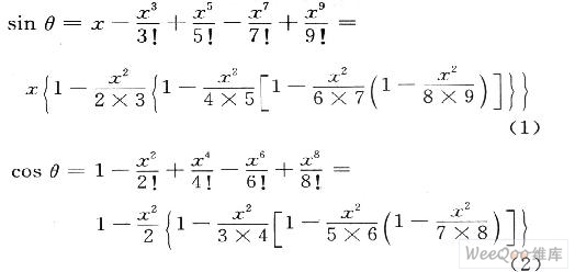
Where: x is the radian value of θ, x=2πf/fs (fs is the sampling frequency; f is the frequency of the signal to be generated).
1.2 Hardware Design
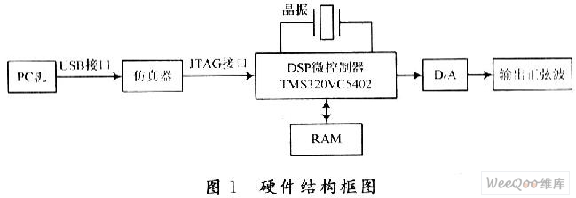
The system hardware mainly consists of a microcomputer, a DSP chip, and a digital/analog conversion module. Among them, the DSP chip used is the TMS320VC5402 with a good cost performance ratio from TI. It has one set of program buses and three sets of data buses, a highly parallel arithmetic logic unit ALU, a dedicated hardware logic on-chip memory, an enhanced HPI port, and a CPU frequency of up to 100 MHz. It can complete two read and one write operations in one cycle, and has a dedicated hardware multiplier, widely uses pipeline operations, and provides special DSP instructions, which can be used to quickly implement various digital signal processing algorithms. The D/A uses a bipolar 8-bit, low-power digital/analog converter DAC08 to achieve high-speed synchronous digital/analog conversion. The hardware structure block diagram is shown in Figure 1.
1.3 Software Design
The software design is based on the CCS development environment. CCS is an integrated development environment launched by TI for the development of TMS320 series DSP software. It is currently one of the most widely used DSP development software. It provides links such as environment configuration, source file compilation, compilation connection, program debugging, tracking analysis, etc., and integrates software and hardware development tools together, so that program writing, assembly, software and hardware simulation and debugging of the program can be carried out in a unified environment, thereby accelerating the software development process. This paper adopts an online programming mode combined with a hardware development board, and implements a sine signal generator by applying C language and C54X assembly language on the CCS software platform. The
idea of software design is: the waveform of a sine wave can be regarded as composed of countless points, which correspond to each angle value of the x-axis. The advantage of the DSP processor in processing a large number of repeated calculations can be used to calculate the y value corresponding to each point on the x-axis (take N points on the x-axis for approximation). The entire system software consists of a main program and a SIN subroutine based on the Taylor expansion method. The corresponding software flow charts are shown in Figures 2 and 3.
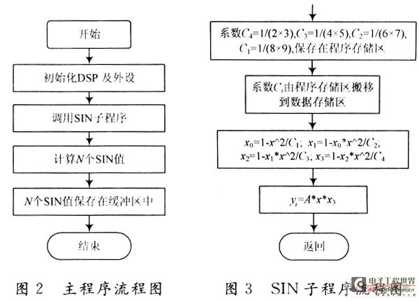
In the program, N is the number of points that generate a cycle of the sine signal. The frequency of the generated sine signal is related to the value of N and the D/A conversion frequency fDA. The calculation formula for generating the frequency f of the sine wave signal is:
f=fDA/N.
Therefore, by selecting the number of sample points in each sine cycle and changing the delay between each sampling point, waveforms of different frequencies can be generated by adjusting the N value. At the same time, the output discrete waveform value can be multiplied by the corresponding scaling factor A by software to adjust the amplitude of the waveform. Load the program into the DSP target chip, and the waveform implementation result can be intuitively displayed in the CCS graphic display interface (see Figure 4) or the output result
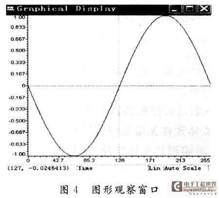
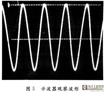
can be observed by an oscilloscope as shown in Figure 5. [page] The output result shows that a sine signal with stable frequency, small signal interference and small waveform distortion is obtained in the CCS graphic observation window; a sine signal with good waveform and stability can also be observed by using an oscilloscope.
2 Design of sine signal generator based on SOPC technology
Although DSP processors (such as TI's TMS320 series) have been almost the only choice for core components of DSP application systems for a long time in the past. However, due to its own limitations, such as inflexible hardware structure, it is difficult to meet the rapidly developing DSP application market today. The emergence of modern large-capacity, high-speed FPGAs with various embedded DSP modules and corresponding SOPC technology has made it easier to implement digital signal processing.
2.1 DDFS Principle
The direct digital frequency synthesis (DDFS) circuit consists of a system clock, a phase accumulator, a frequency accumulator, a waveform lookup table, a D/A converter and a signal conditioning circuit. The working principle of DDFS is that in each clock cycle, the frequency accumulator uses the input frequency word FW as a step to perform self-increment accumulation, and the high bit of the accumulation result is sent to the phase accumulator and accumulated with the input phase word PW. The output of the phase accumulation is used as the address of the waveform lookup table, and the corresponding data is read from the lookup table and sent to the D/A converter. Finally, it passes through a low-pass filter, a post-amplifier and other signal conditioning circuits to form an analog waveform output. Figure 6 shows the system structure block diagram. The

frequency output formula of DDFS is:

Where: N is the bit width of the phase accumulator; M is the bit width of the frequency word; Fclk is the system clock signal.
DDFS generates a sine wave with controllable frequency and phase through a digitally controlled oscillator. Its advantages are that it does not require phase feedback control, the frequency establishment and frequency switching are fast, it is programmable and fully digital, the control is flexible and convenient, and the output phase is continuous. If the number of bits N in the phase accumulator is large enough, a very high resolution accuracy can be obtained in theory. DDFS can also generate a variety of other modulation signals, so it has a very high cost performance.
2.2 Hardware module design and simulation
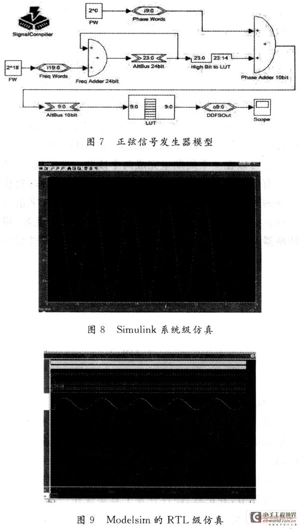
Using DSP Builder to design DSP modules is an integral part of SOPC technology. The key design process is carried out in Matlab's graphical simulation environment Simulink. The graphical module is called in DSP Builder and other Simulink libraries in a graphical way to form a system-level design module, as shown in Figure 7. The
main advantage of modular design is that the frequency and phase of the sine wave can be easily controlled by changing the status word in the module. There is no need to modify it in the program, nor is there a need to understand the complex and difficult-to-master hardware description language. It is truly modular and fully saves design time and design cycle.
After the circuit model design is completed, the powerful graphical simulation verification function of the Simulink environment can be used to directly perform algorithm-level model simulation verification, and the results are shown in Figure 8. Because in Matlab's Simulink, model simulation belongs to the nature of system verification simulation, not RTL-level simulation, and has nothing to do with the target device and hardware system. Therefore, Modelsim is used to perform functional simulation of the designed circuit. Modelsim is an outstanding HDL simulation tool from Mentor. It is widely used for its powerful digital and analog simulation functions, and the simulation results are intuitive and easy to understand, as shown in Figure 9. [page]
From the output waveform results of Figures 8 and 9, it can be seen that the sine wave waveform generated by the sine signal generator designed with the SOPC solution is clear, stable, the phase change is relatively continuous, and the output phase noise is low.
2.3 System hardware verification
The design model file is converted into the corresponding hardware description language VHDL design file through SignaICompiler. In the QuartusⅡ integrated environment,... vhd file is compiled and timed, the design file is simulated and verified, and the input/output corresponding to the PIO in the DE2 development board, i.e., the pin is locked; the device is programmed and finally downloaded to the target chip DE2EP2C35F672C6 to realize hardware testing; Signal-TapⅡ is called to observe the hardware test results, and the waveform output is observed by the oscilloscope after D/A conversion. The result is the same as the system simulation result, thus verifying the rationality of the system design.
3 Conclusion
From the perspective of engineering application, a structured and modular design method based on DSP and SOPC is proposed. This method can be extended to other electronic design fields, making the system circuit design more simple and intuitive, and easy to expand, with high practicality and reliability. By comparing the advantages and disadvantages of DSP and SOPC design, it is shown that compared with DSP design, SOPC technology can greatly shorten the system design cycle, save design costs, and improve the cost performance and competitiveness of products, so it has a better promotion and application prospect.
Keywords:dsp SoPC generator
Reference address:Design of Digital Signal Generator Based on DSP and SOPC
Digital signal generator is a signal generating device and signal source that is widely used in electronic circuit design, automatic control system and instrument measurement, correction and debugging. Sinusoidal signal is a common signal source with the singlest frequency component. Any complex signal (such as sound signal) can be decomposed into the superposition of many sinusoidal signals with different frequencies and amplitudes through Fourier transform. It is widely used in signal processing systems in the fields of electronic technology experiments, automatic control systems and communications, instrumentation, control, and other scientific research fields such as machinery, electroacoustics, hydroacoustics and biology.
At present, most of the commonly used signal generators are composed of analog circuits or digital circuits, with large size and power consumption, and relatively expensive. With the development of microelectronics technology and computer technology, a huge and promising high-tech industry has been formed with DSP microprocessors and DSP software and hardware development systems (such as integrated development environment CCS) and supporting products, and the application of new technologies such as programmable logic devices and SOPC has rapidly penetrated into the fields of electronics, information, and communications. Here, the sine signal generator is designed by taking advantage of the advantages of DSP chip, such as high computing speed, low power consumption, real-time analysis, and flexible configurability, high reliability, and easy hardware upgrade of SOPC technology, and the design process and advantages and disadvantages of each are compared.
1 Design of sine signal generator based on DSP
1.1 Principle of sine wave generation
Generally, there are two methods to generate sine waves: table lookup method and Taylor series expansion method. The table lookup method is a more commonly used method. Its advantages are fast processing speed, easy frequency modulation and phase modulation, high accuracy, but it requires a large memory capacity. The Taylor series expansion method requires fewer storage units, has good stability, simple algorithm, easy programming, etc., and the more series are expanded, the smaller the distortion. This paper adopts the Taylor series expansion method. A sine and cosine function with an angle of θ can be expanded into a Taylor series. Take the first 5 terms to approximate:

Where: x is the radian value of θ, x=2πf/fs (fs is the sampling frequency; f is the frequency of the signal to be generated).
1.2 Hardware Design
The system hardware mainly consists of a microcomputer, a DSP chip, and a digital/analog conversion module. Among them, the DSP chip used is the TMS320VC5402 with a good cost performance ratio from TI. It has one set of program buses and three sets of data buses, a highly parallel arithmetic logic unit ALU, a dedicated hardware logic on-chip memory, an enhanced HPI port, and a CPU frequency of up to 100 MHz. It can complete two read and one write operations in one cycle, and has a dedicated hardware multiplier, widely uses pipeline operations, and provides special DSP instructions, which can be used to quickly implement various digital signal processing algorithms. The D/A uses a bipolar 8-bit, low-power digital/analog converter DAC08 to achieve high-speed synchronous digital/analog conversion. The hardware structure block diagram is shown in Figure 1.

1.3 Software Design
The software design is based on the CCS development environment. CCS is an integrated development environment launched by TI for the development of TMS320 series DSP software. It is currently one of the most widely used DSP development software. It provides links such as environment configuration, source file compilation, compilation connection, program debugging, tracking analysis, etc., and integrates software and hardware development tools together, so that program writing, assembly, software and hardware simulation and debugging of the program can be carried out in a unified environment, thereby accelerating the software development process. This paper adopts an online programming mode combined with a hardware development board, and implements a sine signal generator by applying C language and C54X assembly language on the CCS software platform. The
idea of software design is: the waveform of a sine wave can be regarded as composed of countless points, which correspond to each angle value of the x-axis. The advantage of the DSP processor in processing a large number of repeated calculations can be used to calculate the y value corresponding to each point on the x-axis (take N points on the x-axis for approximation). The entire system software consists of a main program and a SIN subroutine based on the Taylor expansion method. The corresponding software flow charts are shown in Figures 2 and 3.

In the program, N is the number of points that generate a cycle of the sine signal. The frequency of the generated sine signal is related to the value of N and the D/A conversion frequency fDA. The calculation formula for generating the frequency f of the sine wave signal is:
f=fDA/N.
Therefore, by selecting the number of sample points in each sine cycle and changing the delay between each sampling point, waveforms of different frequencies can be generated by adjusting the N value. At the same time, the output discrete waveform value can be multiplied by the corresponding scaling factor A by software to adjust the amplitude of the waveform. Load the program into the DSP target chip, and the waveform implementation result can be intuitively displayed in the CCS graphic display interface (see Figure 4) or the output result


can be observed by an oscilloscope as shown in Figure 5. [page] The output result shows that a sine signal with stable frequency, small signal interference and small waveform distortion is obtained in the CCS graphic observation window; a sine signal with good waveform and stability can also be observed by using an oscilloscope.
2 Design of sine signal generator based on SOPC technology
Although DSP processors (such as TI's TMS320 series) have been almost the only choice for core components of DSP application systems for a long time in the past. However, due to its own limitations, such as inflexible hardware structure, it is difficult to meet the rapidly developing DSP application market today. The emergence of modern large-capacity, high-speed FPGAs with various embedded DSP modules and corresponding SOPC technology has made it easier to implement digital signal processing.
2.1 DDFS Principle
The direct digital frequency synthesis (DDFS) circuit consists of a system clock, a phase accumulator, a frequency accumulator, a waveform lookup table, a D/A converter and a signal conditioning circuit. The working principle of DDFS is that in each clock cycle, the frequency accumulator uses the input frequency word FW as a step to perform self-increment accumulation, and the high bit of the accumulation result is sent to the phase accumulator and accumulated with the input phase word PW. The output of the phase accumulation is used as the address of the waveform lookup table, and the corresponding data is read from the lookup table and sent to the D/A converter. Finally, it passes through a low-pass filter, a post-amplifier and other signal conditioning circuits to form an analog waveform output. Figure 6 shows the system structure block diagram. The

frequency output formula of DDFS is:

Where: N is the bit width of the phase accumulator; M is the bit width of the frequency word; Fclk is the system clock signal.
DDFS generates a sine wave with controllable frequency and phase through a digitally controlled oscillator. Its advantages are that it does not require phase feedback control, the frequency establishment and frequency switching are fast, it is programmable and fully digital, the control is flexible and convenient, and the output phase is continuous. If the number of bits N in the phase accumulator is large enough, a very high resolution accuracy can be obtained in theory. DDFS can also generate a variety of other modulation signals, so it has a very high cost performance.
2.2 Hardware module design and simulation
Using DSP Builder to design DSP modules is an integral part of SOPC technology. The key design process is carried out in Matlab's graphical simulation environment Simulink. The graphical module is called in DSP Builder and other Simulink libraries in a graphical way to form a system-level design module, as shown in Figure 7. The
main advantage of modular design is that the frequency and phase of the sine wave can be easily controlled by changing the status word in the module. There is no need to modify it in the program, nor is there a need to understand the complex and difficult-to-master hardware description language. It is truly modular and fully saves design time and design cycle.
After the circuit model design is completed, the powerful graphical simulation verification function of the Simulink environment can be used to directly perform algorithm-level model simulation verification, and the results are shown in Figure 8. Because in Matlab's Simulink, model simulation belongs to the nature of system verification simulation, not RTL-level simulation, and has nothing to do with the target device and hardware system. Therefore, Modelsim is used to perform functional simulation of the designed circuit. Modelsim is an outstanding HDL simulation tool from Mentor. It is widely used for its powerful digital and analog simulation functions, and the simulation results are intuitive and easy to understand, as shown in Figure 9. [page]
From the output waveform results of Figures 8 and 9, it can be seen that the sine wave waveform generated by the sine signal generator designed with the SOPC solution is clear, stable, the phase change is relatively continuous, and the output phase noise is low.

2.3 System hardware verification
The design model file is converted into the corresponding hardware description language VHDL design file through SignaICompiler. In the QuartusⅡ integrated environment,... vhd file is compiled and timed, the design file is simulated and verified, and the input/output corresponding to the PIO in the DE2 development board, i.e., the pin is locked; the device is programmed and finally downloaded to the target chip DE2EP2C35F672C6 to realize hardware testing; Signal-TapⅡ is called to observe the hardware test results, and the waveform output is observed by the oscilloscope after D/A conversion. The result is the same as the system simulation result, thus verifying the rationality of the system design.
3 Conclusion
From the perspective of engineering application, a structured and modular design method based on DSP and SOPC is proposed. This method can be extended to other electronic design fields, making the system circuit design more simple and intuitive, and easy to expand, with high practicality and reliability. By comparing the advantages and disadvantages of DSP and SOPC design, it is shown that compared with DSP design, SOPC technology can greatly shorten the system design cycle, save design costs, and improve the cost performance and competitiveness of products, so it has a better promotion and application prospect.
Previous article:Design of high frequency sine wave generator based on DDS technology
Next article:Design of digital oscilloscope based on equivalent and real-time sampling
- Popular Resources
- Popular amplifiers
Recommended Content
Latest Test Measurement Articles
- Keysight Technologies Helps Samsung Electronics Successfully Validate FiRa® 2.0 Safe Distance Measurement Test Case
- From probes to power supplies, Tektronix is leading the way in comprehensive innovation in power electronics testing
- Seizing the Opportunities in the Chinese Application Market: NI's Challenges and Answers
- Tektronix Launches Breakthrough Power Measurement Tools to Accelerate Innovation as Global Electrification Accelerates
- Not all oscilloscopes are created equal: Why ADCs and low noise floor matter
- Enable TekHSI high-speed interface function to accelerate the remote transmission of waveform data
- How to measure the quality of soft start thyristor
- How to use a multimeter to judge whether a soft starter is good or bad
- What are the advantages and disadvantages of non-contact temperature sensors?
MoreSelected Circuit Diagrams
MorePopular Articles
- LED chemical incompatibility test to see which chemicals LEDs can be used with
- Application of ARM9 hardware coprocessor on WinCE embedded motherboard
- What are the key points for selecting rotor flowmeter?
- LM317 high power charger circuit
- A brief analysis of Embest's application and development of embedded medical devices
- Single-phase RC protection circuit
- stm32 PVD programmable voltage monitor
- Introduction and measurement of edge trigger and level trigger of 51 single chip microcomputer
- Improved design of Linux system software shell protection technology
- What to do if the ABB robot protection device stops
MoreDaily News
- Allegro MicroSystems Introduces Advanced Magnetic and Inductive Position Sensing Solutions at Electronica 2024
- Car key in the left hand, liveness detection radar in the right hand, UWB is imperative for cars!
- After a decade of rapid development, domestic CIS has entered the market
- Aegis Dagger Battery + Thor EM-i Super Hybrid, Geely New Energy has thrown out two "king bombs"
- A brief discussion on functional safety - fault, error, and failure
- In the smart car 2.0 cycle, these core industry chains are facing major opportunities!
- The United States and Japan are developing new batteries. CATL faces challenges? How should China's new energy battery industry respond?
- Murata launches high-precision 6-axis inertial sensor for automobiles
- Ford patents pre-charge alarm to help save costs and respond to emergencies
- New real-time microcontroller system from Texas Instruments enables smarter processing in automotive and industrial applications
Guess you like
- Who remembers a video about the principles of network communication?
- [Sipeed LicheeRV 86 Panel Review] 7 - lvgl Solution to the problem of incorrect image color display
- Wireless communication technology-NB-IoT
- SMT32 is no longer available, let's discuss alternative models
- Robotics (Stanford University Open Course)
- [Anxinke UWB indoor positioning module NodeMCU-BU01] 01: Module appearance interface, onboard resources and power supply characteristics
- ESD204 surge protection for HDMI interface
- Last day! Pre-register to win a JD card! 60 cards in total! Rohm live broadcast: How to use laser diodes well
- Based in Chengdu, job opening: RF chip test engineer
- CircuitPython 4.0.2 released

 LM108AHLQMLV


 京公网安备 11010802033920号