introduction
Embedded systems are application-centric, computer-based, and specialized computer systems that can adapt to strict requirements on functionality, reliability, cost, size, power consumption, etc. in practical applications. They are the product of the combination of advanced computer technology, semiconductor technology, and electronic technology with specific applications in various industries. In some specific areas, they are required to respond to external requests in real time and process corresponding calculations, and finally feedback the results to users or peripherals in a timely manner. With the rapid expansion of embedded application fields, people have put forward higher requirements for the quality of embedded software. How to quickly and effectively test increasingly complex embedded software has become a hot topic.
1 Design Principle
1.1 System Requirements
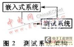
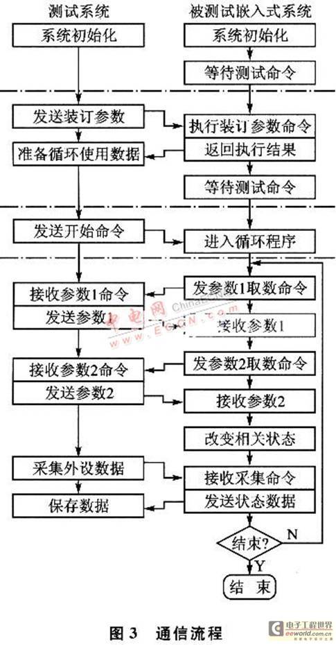
The embedded system under test used in this paper is shown in Figure 1. It is an embedded system running flight control software. It needs to calculate the flight attitude and trajectory, and interact with the servo, engine, seeker, and inertial measurement unit through the bus. The object of the test is the flight control software running on the embedded platform, and the remaining peripherals are simulated by the test system. This paper mainly discusses the design and implementation of the test system. The core device used in the embedded system is the DSP chip, which has multiple interfaces, including 1 A/D, 1 D/A, 8 switch quantities, 2 serial 422 interfaces, and 2 serial 485 interfaces. The required functions are completed through the communication of various interfaces. After the system is running, it will be in a state of completing one interaction with the peripherals every 5ms for a long time, where one interaction includes two requests to send and receive data (status and control data), and transmit all switch quantities and A/D data. The specific requirements of the test system are as follows: First, the industrial computer (simulated by the test system, as shown in Figure 2) sends the binding parameters to the embedded device; then, the embedded device is initialized according to the binding parameters and is in a waiting command state; the industrial computer sends a start command to the embedded device; after receiving the start command, the embedded device enters a periodic cycle state.

Cycle status:
① The embedded system will request peripheral 1 control data from external device 1 (simulated by the test system), and external device 1 needs to send the data to the embedded system within 2 ms.
②The embedded system will request peripheral 2 control data from external device 2 (simulated by the test system), and external device 2 needs to send the data to the embedded system within 2 ms.
③ The host computer (simulated by the test system) needs to complete the acquisition of relevant data of the embedded system within 1 ms after sending the control data of peripheral 2. The entire cycle period is required to be strictly controlled within 5 ms.
The communication process is shown in Figure 3.
1.2 Design Concept
To design a test system that meets the needs, there are five requirements for the test system: first, it must be able to respond to DSP data requests in an interrupt manner in a timely manner; second, it must have sufficient performance to parse and send data; third, it must have a good human-computer interaction interface; fourth, it must be able to manage tested use cases and results; and fifth, it must be able to flexibly add faults, such as communication failures, instruction failures, and data failures.
The high real-time requirements greatly increase the complexity of the system and limit the available solutions when designing the test system. Windows is a time-sharing operating system, and its ability to handle interrupts is not very stable, and sometimes it will not meet the requirements of embedded systems. In addition, the timer accuracy of the time-sharing operating system is poor, the drift phenomenon is serious, and there are implicit uncertain threads.
Scheduling mechanism. However, some advanced features of the Windows operating system are required, such as powerful graphical interface (GUI) support, support for a variety of development tools and applications, support for many cheap third-party hardware and drivers, and rich Win32 application programming interfaces.
RTX (Real-tline Extension for Control of Windows) adds a real-time extension subsystem (RTSS) to the Windows platform. Its independent preemptive RTX thread scheduling mechanism allows RTSS threads to take precedence over all Windows threads and interrupts, with a continuous interrupt response frequency of more than 30 kHz and a maximum IST processing delay of no more than 16μs. It provides high-speed and accurate real-time time response, with a minimum timer period of 100μs and a minimum clock resolution of 100 ns. It is particularly suitable for typical control servo systems that require both graphics and real-time requirements, such as flight simulators, complex video surveillance systems, video image processing, turntables, robots, missile launchers, artillery, etc. It is a hard real-time solution based on the Windows platform. Wirldows processor
The real-time extension subsystem is used for real-time control and real-time data collection. The data transmission mechanism between them is realized through inter-process communication, using shared memory, semaphore and other mechanisms. [page]
Based on the above considerations, two design schemes are proposed.
2 Design
2.1 Windcws+RTX (industrial computer+interface card)
The Windows+RTX solution is shown in Figure 4. The software part of this design is divided into three layers.
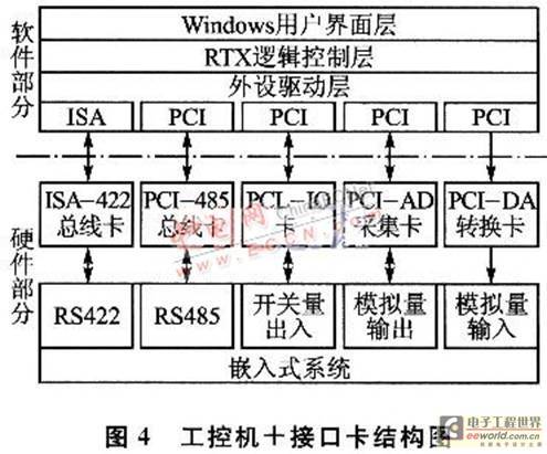
Windows user interface layer. Develop some software on the Windows operating system, responsible for database management, adding use cases, saving running results, and providing a set of excellent interfaces to present to users.
RTX logic control layer. Mainly responsible for the use case operation, interacting with the system under test in real time, meeting the requests for relevant data of the system under test, and saving the status data sent by the system under test.
Peripheral driver layer. In order to meet 100% testing of the system, a communication interface card between the test system and the system under test is also required. From the hardware point of view, it includes 1 industrial computer, 2 ISA bus RS422 communication cards, 2 PCI bus RS485 communication cards, 1 A/D card, switch quantity acquisition card, and D/A card. These hardware boards are connected to the test platform through ISA and PCI buses. The test platform manages the drivers of all boards to form a closed loop with the system under test.
In this way, the three-layer software structure can run the use cases smoothly and achieve complete functional testing of the system.
2.2 Windows+Verilog (industrial computer+FPGA board+interface chip)
The second solution uses Windows+Verilog, as shown in Figure 5. In this solution, FPGA is used to manage various interfaces and communicate with the industrial computer through the PCI bus. The PCI bus can upload data from various interfaces to the industrial computer and download data from the industrial computer to the system under test. [page]
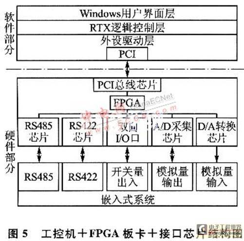
The system also has a three-layer structure. The top two layers are basically the same as the first solution, but the peripheral driver layer no longer fetches and sends data between multiple boards. Instead, it communicates with the FPGA board through a single established protocol, and the subsequent interface chip acquisition, encoding and other tasks are all completed by the FPGA.
3. Comparison of solutions
3.1 Comparison of the advantages and disadvantages of the two solutions
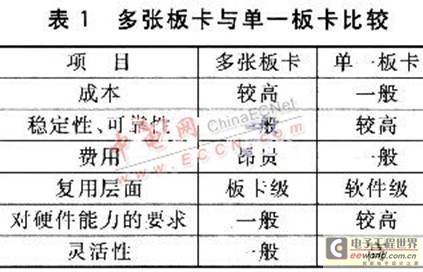
Table 1 compares the advantages and disadvantages of the above two solutions in detail. In the second design, because of the FPGA device, the original ill-considered design can be modified by reconfiguring the hardware, reducing the cycle and cost of re-printing and other uncertain factors, and achieving a wider range of testing purposes.
3.2 Comparison of advantages and disadvantages of different operating systems
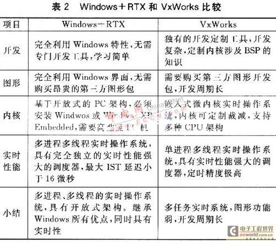
In addition, the implementation of the solution can also consider running some real-time operating systems directly on the industrial computer, such as DOS, VxWorks, etc. DOS is a single-task real-time system with a poor human-computer interaction interface and no network function. Table 2 compares the advantages and disadvantages of the two solutions of Windows+RTX and VxWorks.
4 Use Case Management Software Design
At the upper level of the software, a use case management system with a database needs to be designed. It needs to manage the definition, introduction, group, running time, process data, and result data of the use case, and can act as the use case management layer for regression testing. Before the use case runs, it is necessary to collect various parameters entered by the user, and read the relevant data from the corresponding file location into the memory in advance to prepare the data in advance. When the use case runs, the RTX layer will have corresponding CPU idle time, and the use case management layer will use this time to display the running status. After the use case runs, the corresponding flag will be set. After reading the corresponding status, the use case management layer will actively ask the RTX layer for various running data and results, and store the corresponding data in the database, write the log, and present it on the interface.
Conclusion
The test proves that the test system designed above runs well during the whole machine joint debugging process and meets the requirements of comprehensive testing of the functions of each module of the system. Aiming at the current hot issue of embedded system testing, this paper proposes a structural framework of a real-time embedded software test system, and implements a test system for black box (functional) testing according to this idea. The next step is to develop a universal test platform for embedded software, which can test embedded systems of various models and interfaces at the same time. This solution is also suitable for video image processing and video surveillance systems.
Previous article:Design principles and testing of LD0, QLDO and VLDO
Next article:Research on the Implementation of Torsional Vibration Signal Measurement System Based on SOPC
Recommended ReadingLatest update time:2024-11-15 14:43


- Popular Resources
- Popular amplifiers
-
 Analysis and Implementation of MAC Protocol for Wireless Sensor Networks (by Yang Zhijun, Xie Xianjie, and Ding Hongwei)
 -
 MATLAB and FPGA implementation of wireless communication
 -
 Intelligent computing systems (Chen Yunji, Li Ling, Li Wei, Guo Qi, Du Zidong)
 -
 Summary of non-synthesizable statements in FPGA
- From probes to power supplies, Tektronix is leading the way in comprehensive innovation in power electronics testing
- Seizing the Opportunities in the Chinese Application Market: NI's Challenges and Answers
- Tektronix Launches Breakthrough Power Measurement Tools to Accelerate Innovation as Global Electrification Accelerates
- Not all oscilloscopes are created equal: Why ADCs and low noise floor matter
- Enable TekHSI high-speed interface function to accelerate the remote transmission of waveform data
- How to measure the quality of soft start thyristor
- How to use a multimeter to judge whether a soft starter is good or bad
- What are the advantages and disadvantages of non-contact temperature sensors?
- In what situations are non-contact temperature sensors widely used?
- LED chemical incompatibility test to see which chemicals LEDs can be used with
- Application of ARM9 hardware coprocessor on WinCE embedded motherboard
- What are the key points for selecting rotor flowmeter?
- LM317 high power charger circuit
- A brief analysis of Embest's application and development of embedded medical devices
- Single-phase RC protection circuit
- stm32 PVD programmable voltage monitor
- Introduction and measurement of edge trigger and level trigger of 51 single chip microcomputer
- Improved design of Linux system software shell protection technology
- What to do if the ABB robot protection device stops
- Analysis of the application of several common contact parts in high-voltage connectors of new energy vehicles
- Wiring harness durability test and contact voltage drop test method
- From probes to power supplies, Tektronix is leading the way in comprehensive innovation in power electronics testing
- From probes to power supplies, Tektronix is leading the way in comprehensive innovation in power electronics testing
- Sn-doped CuO nanostructure-based ethanol gas sensor for real-time drunk driving detection in vehicles
- Design considerations for automotive battery wiring harness
- Do you know all the various motors commonly used in automotive electronics?
- What are the functions of the Internet of Vehicles? What are the uses and benefits of the Internet of Vehicles?
- Power Inverter - A critical safety system for electric vehicles
- Analysis of the information security mechanism of AUTOSAR, the automotive embedded software framework
- msp430f5529lp driver problem
- [Evaluation of domestic FPGA Gaoyun GW1N-4 series development board]——3. Turn on a lamp hello_led
- When opening the project, it prompts that there is no RAA305190GBM_common.xml
- Could you please help me with how to calculate the VGS of this current mirror? Thank you very much!
- GigaDevice's new GD32F470xx series with TFT and Ethernet port
- MicroPython adds support for operator @
- I would like to ask you about the ODB protocol dedicated chip
- 【GD32L233C-START Review】1. Unboxing
- Frequency calculation
- A detailed introduction to the control technology of various DC motors

 Analysis and Implementation of MAC Protocol for Wireless Sensor Networks (by Yang Zhijun, Xie Xianjie, and Ding Hongwei)


 京公网安备 11010802033920号