Radio frequency identification based on surface acoustic wave [1] is an emerging technological achievement that integrates modern electronics, acoustics and radar signal processing. It is another new type of non-contact identification technology different from IC chip identification and is considered to be one of the ten technologies with the greatest application potential in the 21st century. Traditional RFID systems based on IC tags are used in high temperature and strong electromagnetic interference environments, which makes it difficult to read information, resulting in a high tag failure rate or even failure to work properly. Since SAW devices work in the radio frequency band, are passive and wireless, have a long reading distance and strong environmental adaptability, and have the dual functions of ID identification and sensor, they can obtain various physical indicators of the target, such as temperature, pressure and gas concentration, while identifying the ID, and have broad market prospects. This paper designs and uses a surface acoustic wave radio frequency identification system to realize the ID identification and temperature measurement of the object being measured, and creatively applies it to mine monitoring.
1 SAW RFID system principle and composition
A complete SAW RFID terminal system [2] consists of three parts: SAW tag, reader and application system, as shown in Figure 1. The reader is a device that has the function of transmitting, receiving and processing radio frequency signals. The passive SAW tag is placed on the surface of the object to be identified and is used to measure the relevant information of the object to be measured. The reader transmits a radio frequency signal of a certain frequency through the antenna. When the tag enters the reader's working area, the electromagnetic wave emitted by the reader activates the tag circuit. The tag's energy detection circuit converts part of the radio frequency signal into DC signal energy for its operation. After the tag obtains energy and is activated, it modulates its own serial number and other information onto the radio frequency signal, and then sends it out through the tag antenna. After receiving the radio frequency signal returned by the tag, the reader demodulates and decodes the signal and then sends it to the background main system for relevant processing. The main system determines the legitimacy of the tag based on logical operations and makes corresponding processing and control for different settings.

2 SAW RFID system design
2.1 SAW tag design
SAW RFID tags[3] are mainly composed of an interdigital transducer, a piezoelectric substrate, a reflective grating and an antenna.
The signal appears in the form of surface acoustic waves in the tag and propagates on the surface of the substrate. When the temperature of the object being measured changes, the surface acoustic wave will have a frequency deviation. At the same time, the changed surface acoustic wave will be engraved on the reflective grating of the tag according to a certain coding rule, and reflected back to form a series of acoustic pulse trains. Since the reflective grating is designed according to a certain rule, its reflected signal represents the specified coding information. The reflected high-frequency electric pulse train received by the reader carries the specific code of the object. Through analysis and processing, the coding information of the reflective grating is demodulated to achieve the purpose of automatic identification. At the same time, the frequency deviation value is extracted according to the FFT algorithm to further obtain the temperature information of the object being measured.
2.2 RF front-end module design
Traditional RFID transceivers use a superheterodyne receiver structure, which is costly, complex, difficult to integrate, and has high power consumption. Combining the characteristics of zero intermediate frequency [4], this paper adopts a zero intermediate frequency structure, including a local oscillator, a transmitting module, and a receiving module, to overcome the image frequency interference and reduce the development cost.
2.2.1 Design of the transmitting circuit
The 915 MHz transmitting circuit is shown in Figure 2. The LT5519 chip is used as the up-conversion mixer, and the RF output bandwidth is 0.7 GHz~1.4 GHz. The π-type attenuator is designed using CASCADE software, R1=24 Ω, R2=R3=220 Ω, and the attenuation is 4 dB. The bandpass filter uses B4637, with a center frequency of 915 MHz, a bandwidth of 26 MHz, and an insertion attenuation of 2.5 dB. The adjustable gain amplifier (VGA) uses Sky65111, with an input bandwidth of 600 MHz~1 100 MHz. According to the distance between the tag and the reader, the automatic gain control (AGC) module adaptively adjusts the gain of the VGA so that the reader can correctly receive the information returned by the tag, and the maximum output power reaches 33 dBm@915 MHz.
2.2.2 Design of receiving circuit
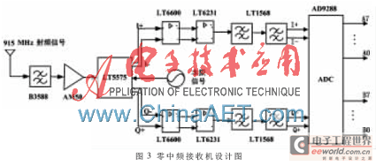
The reader of this system is designed with a zero intermediate frequency structure [5]. It mainly includes an orthogonal demodulator and AD sampling. The receiving circuit is shown in Figure 3.
After the tag return signal from the antenna is processed by the RF front end, a bandpass filter is used to suppress signals outside the 915 MHz~925 MHz frequency band, and a low noise amplifier amplifies the signal for back-end processing. The amplified signal enters the LT5575 mixer demodulator, and the up and down conversion uses the same frequency local oscillator signal. The down-converted signal is the I/Q orthogonal baseband signal. After amplification and filtering, it enters the AD9288 for AD sampling and conversion into a digital baseband signal, and the DSP decodes the received baseband signal and other processing.

2.2.3 Design of local oscillator
ADI's ADF4360-7 is used, and an external 10 MHz high-precision temperature-compensated crystal oscillator is used as the reference frequency. By selecting the corresponding working mode, the output signal frequency range is 350 MHz~1 800 MHz. In the design of the local oscillator of this system, a 915 MHz RF signal is generated in the form of a digital phase-locked loop, which is used as the local oscillator signal of the up and down mixing circuits respectively. The important parameters of the loop filter, including the phase detection frequency, output frequency, bandwidth and order, are designed using the ADIsimPLL software, and the design diagram of the local oscillator is obtained, as shown in Figure 4. In addition, with the help of the software ADF4360.exe, the parameters such as the VOC output frequency, phase detection frequency and frequency division modulus are set, and the values of the internal C, N and R registers are configured, which reduces the difficulty of developing the PLL driver.

2.3 Baseband main control module design
The DSP baseband main control unit is the control core of the entire system. The detailed functional block diagram is shown in Figure 5.

The DSP module uses TI's TMS320VC5509A chip [6]. After power-on, the program in the EEPROM is loaded into the chip by running the Boatload program to control the operation of each module. The power and clock modules provide the system with stable power and accurate external reference clock. The PLL is controlled to generate the local oscillator signal and provide it to the RF front-end module. The external storage module composed of SDRAM and EEPROM is responsible for data processing and program storage respectively. The CPLD mainly receives bus information from the DSP, and reprocesses the bus signal logically to expand the DSP's I/O port for output control. The automatic gain control (AGC) adaptively adjusts the signal power according to the card reading distance to increase the reliability of the system. The LCD module intuitively displays the results of DSP decoding, verification and other processing. In addition, the serial port network port module serves as a communication interface for data exchange with the host computer.
The working process of the main control core DSP is as follows: (1) The system is powered on and the program in the EEPROM is loaded into the chip to start running; (2) The DSP initializes the control registers of the GPIO port, interrupt, timer, etc. according to the program settings; (3) The PLL is programmed to output the local oscillator signal to achieve modulation and demodulation; (4) The instructions to be output are encoded and sent out from the corresponding general output port of the DSP; (5) The AD module is controlled to perform AD conversion, decode and verify the digital baseband signal. If the verification is correct, the corresponding operation is performed, and finally the result is sent to the LCD or host computer for other processing, otherwise it goes to the second step for further processing.
3 Experimental data and analysis
3.1 SAW Tags
Figure 6 shows the SAW tag mentioned in this article, where Figure 6(a) is the wafer of the tag, and Figure 6(b) is the finished tag. Compared with traditional packaging, wafer-level packaging is used to achieve full packaging of the surface acoustic wave tag IDT. All effective graphics are protected in the cavity, avoiding problems such as short circuit failure caused by various situations in the later stage, improving the reliability of the device, and realizing one-time packaging of the entire piece, improving the consistency of the product, and being suitable for mass production. Figure 6(c) shows that the SAW RFID tag is small in size and easy to install and use.

3.2 RFID Reader
The SAW RFID reader mentioned in this article is mainly divided into four circuit boards: power board, transmitter board, receiver board and DSP main control board. The C5509 processor sends the tag read and write signal, controls the transmitter to send a 915 MHz interrogation pulse, and the receiver performs filtering, amplification, AD conversion and other related processing on the RF signal returned by the tag, and converts it into a digital baseband signal. The C5509 processor decodes and extracts the frequency deviation of the received baseband signal, further obtains the ID and temperature information of the object being measured, and uploads it to the host computer for further statistical analysis. Compared with ordinary RFID systems, this system can quickly and accurately read the ID and temperature information of the object being measured, and can work normally in an environment with high temperature difference, high humidity and strong electromagnetic interference.
3.3 System Testing
A SAW RFID system was built and its functionality tested.
After connecting the hardware system, open the test software, as shown in Figure 7, set the communication parameters such as communication port and baud rate, check the SAW tag to be tested and the corresponding antenna, click Start, and you can observe the real-time ID and temperature information. Heat one of the SAW tags and you can observe the dynamic change of temperature (47.60℃). The test results show that the minimum sampling interval can reach 50 ms, the effective recognition distance is about 5 m~10 m, the temperature measurement range is 0~125℃, the accuracy can reach 0.01℃, and the error is 1℃.

4 Applications of SAW RFID
SAW RFID has the advantages of being wireless and passive, having a long identification distance and high speed, and being highly adaptable to the environment. It can be used to measure changes in parameters such as pressure and temperature. In view of the complex underground environment of coal mines, the requirements of temperature monitoring and personnel positioning, etc., the system is applied to the comprehensive safety supervision of coal mines [7], realizing real-time monitoring of underground equipment and environmental parameter information, as well as the positioning and tracking of personnel, effectively preventing safety accidents and improving production efficiency. The raw materials of the system are relatively cheap, suitable for mass production, and easy to use. In the current period when mine accidents are relatively frequent, it has great use value and market potential.
This paper introduces the working principle of SAW RFID from the perspective of its composition structure, and elaborates on the key technologies in the design process of SAW RFID reader, focusing on the design of the RF front end, including the hardware design of the transmitting module, receiving module and local oscillator, and also gives the design block diagram and algorithm flow of the DSP baseband main control module. By analyzing the test data, it is proved that the working performance of the designed system is reliable and stable, and the design idea is indeed feasible. Finally, combining the advantages of this SAW RFID system, it is applied to mine monitoring, playing a huge role in underground personnel management and emergency rescue.
References
[1] HAGELAUER A, USSMUELLE T, WEIGEL R. SAW and CMOS RFID Transponder-Based wireless systems and their applications[C]. Frequency Control Symposium(FCS) 2012,IEEE International, 2013,3,21-24:1-6 .
[2] Wang Yulin, Cao Jinrong, Qianfeng, et al. Surface acoustic wave radio frequency identification passive electronic tag[J]. Research and Progress in Solid State Electronics, 2007, 27(1):109-114.
[3] Li Qingliang. Research on surface acoustic wave radio frequency identification tags and systems[D]. Shanghai: Shanghai Jiaotong University, 2008.
[4] Fan Jialin. Design of 915 MHz card reader[D]. Dalian: Dalian University of Technology, 2006.
[5] Zhao Lei, Xiao Mahui, Deng Tengbin, et al. Design of zero intermediate frequency receiver in UHF RFID reader/writer[J]. Internet of Things Technology, 2011(8):47-49.
[6] Texas Instruments. TMS320VC5509A Fixed-Point Digital Signal Processor Data Manual [Z]. 2006.
[7] Li Zhi, Jiang Huiqiang. A coal mine personnel positioning system based on RFID[J]. Microprocessor, 2012, 6(3): 84-86.
Previous article:Design of a cochlear implant speech processor based on DSP
Next article:Application of DSP+FPGA in high-speed and high-precision motion controller
- Popular Resources
- Popular amplifiers
- Huawei's Strategic Department Director Gai Gang: The cumulative installed base of open source Euler operating system exceeds 10 million sets
- Analysis of the application of several common contact parts in high-voltage connectors of new energy vehicles
- Wiring harness durability test and contact voltage drop test method
- Sn-doped CuO nanostructure-based ethanol gas sensor for real-time drunk driving detection in vehicles
- Design considerations for automotive battery wiring harness
- Do you know all the various motors commonly used in automotive electronics?
- What are the functions of the Internet of Vehicles? What are the uses and benefits of the Internet of Vehicles?
- Power Inverter - A critical safety system for electric vehicles
- Analysis of the information security mechanism of AUTOSAR, the automotive embedded software framework
 Professor at Beihang University, dedicated to promoting microcontrollers and embedded systems for over 20 years.
- LED chemical incompatibility test to see which chemicals LEDs can be used with
- Application of ARM9 hardware coprocessor on WinCE embedded motherboard
- What are the key points for selecting rotor flowmeter?
- LM317 high power charger circuit
- A brief analysis of Embest's application and development of embedded medical devices
- Single-phase RC protection circuit
- stm32 PVD programmable voltage monitor
- Introduction and measurement of edge trigger and level trigger of 51 single chip microcomputer
- Improved design of Linux system software shell protection technology
- What to do if the ABB robot protection device stops
- Allegro MicroSystems Introduces Advanced Magnetic and Inductive Position Sensing Solutions at Electronica 2024
- Car key in the left hand, liveness detection radar in the right hand, UWB is imperative for cars!
- After a decade of rapid development, domestic CIS has entered the market
- Aegis Dagger Battery + Thor EM-i Super Hybrid, Geely New Energy has thrown out two "king bombs"
- A brief discussion on functional safety - fault, error, and failure
- In the smart car 2.0 cycle, these core industry chains are facing major opportunities!
- The United States and Japan are developing new batteries. CATL faces challenges? How should China's new energy battery industry respond?
- Murata launches high-precision 6-axis inertial sensor for automobiles
- Ford patents pre-charge alarm to help save costs and respond to emergencies
- New real-time microcontroller system from Texas Instruments enables smarter processing in automotive and industrial applications
- CC2500 Migration Instructions
- [DWIN Serial Port Screen] Nucleic Acid Sampling Registration System 2: Prepare Background Image
- VIAVI's latest report shows: 5G services now cover 1,662 cities around the world. Have you felt it? ? ?
- Switching Power Supply Interest Group 11th Task
- The zigbee terminal sets the PAN ID by pressing a button to join the set ID network
- Far away, yet close at hand
- The power cord is too long and the power-on voltage is too high. Should I use a TVS tube?
- What is the essence of GND in the circuit?
- EEWORLD University - i.MX Linux Development Practical Guide
- Encoder Problems

 TLV2254QPWRQ1


 京公网安备 11010802033920号