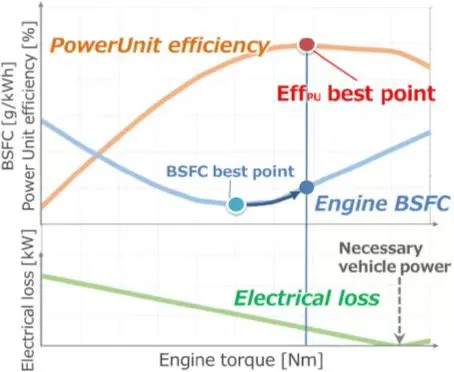
Figure 7-3 System maximum efficiency
3. Hybrid mode enhances driving performance
3.1 Improve driving performance-Engine economical operation
Hybrid mode enhances driving performance by ensuring control in the following two aspects.
3.1.1 The driving force is provided by the drive motor, and the engine is decoupled and operated in the extended-range mode;
3.1.2 Control to ensure that the engine operates at the optimal efficiency point.
The specific engine operation line is shown in Figure 7-4.
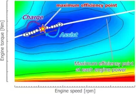
Figure 7-4 Hybrid driving engine operation line
3.2 Improving driving performance - reasonable relationship between vehicle speed and rotation speed
Linear shift control is used to simulate the transmission upshift operation and reduce the discomfort during driving. See Figure 7-5 for details.
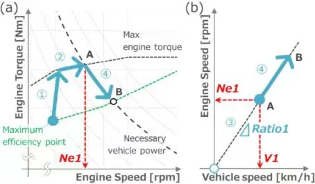
Figure 7-5 Vehicle speed and engine speed relationship
High driving force is required, and the torque edge is used first to avoid unnecessary increase in engine speed, such as a-①;
The power continues to increase, exceeding the current engine power + battery power, and the engine speed increases to Ne1, such as a-②. At this time, the ratio of Ne1/V1 is 1, and the engine speed is controlled to follow and maintain the vehicle speed growth rate. At this time, the ratio of the engine speed to the vehicle speed is set to ratio 1. The size of ratio 1 is selected according to the engine speed usage requirements and NVH requirements;
As the vehicle speed continues to increase, if the ratio is maintained at 1, the engine speed will continue to rise, and the engine speed needs to be reduced by shifting gears. When to perform the gear shift should be determined based on the vehicle speed and engine speed. At this time, the engine speed is in the ratio 1 state and uses the upper limit speed. After the gear shift, the engine speed and vehicle speed ratio 2 is formed. Ratio 2 is less than ratio 1, so that the engine speed is reduced at the same vehicle speed. The gear shift is performed (④) to actively control the engine speed to avoid driving performance discomfort caused by high engine speed at high vehicle speed.
3.3 Improve driving performance - speed and vehicle speed ratio following
Based on the above reasonable correlation between vehicle speed and rotation speed, the following is a detailed description of the engine speed and vehicle speed ratio following, as shown in Figure 7-6.
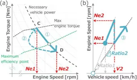
Figure 7-6 Vehicle speed and engine speed proportionality following
The engine speed and vehicle speed follow the proportional principle according to the following items:
3.3.1 Ensure vehicle driving requirements, achieve vehicle required power, and shift the engine power line toward high torque;
3.3.2 Define the most sensitive speed limit and limit the maximum engine speed corresponding to this speed;
3.3.3 Define the proportional change between engine speed and vehicle speed, and define the proportional limit requirements, such as Proportional 1, Proportional 2, Proportional 3, etc. Multiple proportional changes can be defined as needed.
Control the ratio of engine speed to vehicle speed change to achieve the effect that the increase in engine speed reasonably follows the increase in vehicle speed and meet the requirement of high engine speed use at high vehicle speed.
First, the engine speed follows the vehicle speed ratio 1. As the vehicle speed increases, the engine speed gradually increases until it reaches the engine speed limit Ne1 under ratio 1.
If the vehicle speed continues to increase, the engine speed will continue to rise, and it will gradually deviate from Ne1 (as shown in a-①);
When the deviation exceeds the maximum limit of engine speed, the engine speed is Ne2;
The engine speed reduction measures must be implemented, and the gear shifting operation is adopted to reduce the engine speed to Ne1 again (as shown in a-②);
The ratio changes as Ne1/V1→Ne2/V2→Ne1/V2…, and a reasonable engine speed and vehicle speed growth following ratio is defined based on the design requirements and vehicle performance requirements.
During the entire operation, the changes in the ratio of engine speed to vehicle speed are defined according to relevant standards and specifications based on various conditions such as vehicle model, performance requirements, NVH requirements, and engine requirements.
3.4 Improving driving performance - engine speed during gear shifting
Honda's latest generation of hybrid vehicles adopts a two-speed design, which can match heavier vehicles and improve the vehicle's power performance. The engine speed can be adjusted during the gear shifting process, mainly following the following principles.
3.4.1 Achieve better acceleration, while engine speed control adjustment meets expected requirements;
3.4.2 The engine tends to be used at high load and high torque, that is, the engine is used at high load first to avoid the engine speed convexity;
3.4.3 Follow the engine's best economic point, and keep the gear shift linear, so as to achieve both acceleration enhancement and economy. The gray dotted line is the previous generation single-gear IMMD hybrid system. As the vehicle speed changes, the engine speed increases with the vehicle speed. After reaching a certain speed, the engine speed remains stable and unchanged; the new generation IMMD hybrid system adopts a two-gear design. The engine transmission can achieve two gear selection outputs. In the starting process, in order to meet better acceleration, the first gear with a large transmission ratio is used. The engine speed increases with the vehicle speed at low speeds. When the vehicle speed reaches a certain speed, the engine speed increases to the limit, and the gear is shifted. The second gear with a relatively small transmission ratio is used to maintain the engine speed increase range, so that the engine speed will not be used at high speeds, and the engine will not run at high speeds at low speeds. See Figure 7-7 for details.
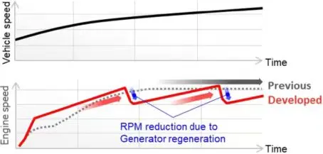
Figure 7-7 Engine speed changes during gear shifting
4. Hybrid mode enhances driving performance
4.1 Increase vehicle speed while taking into account power
4.1.1 Increase the motor speed. The maximum motor speed is increased from the original 13000rpm to 145000rpm, which can further increase the maximum vehicle speed;
4.1.2 The hybrid box adopts two-speed technology to achieve better vehicle acceleration and higher vehicle speed performance, taking into account both vehicle speed and power;
4.1.3 The new drive motor has greater torque and higher speed, achieving 0.4g acceleration for the vehicle starting, as shown in Figure 7-8.
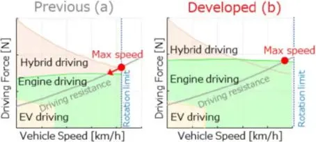
Figure 7-8 Comparison of maximum vehicle speed before and after improvement
4.2 Improving motor operation performance
4.2.1 In the original state, the engine and the motor share a local output gear. The engine transmission ratio must be considered, and the gear ratio configuration needs to be taken into account, which is not conducive to the output effect of the motor;
4.2.2 The new generation of hybrid system motors are individually configured with transmission ratios, and the motor output ratio is matched according to its own performance requirements, which can achieve better motor power performance;
4.2.3 At the same time, the new generation of hybrid system motor operating conditions are better, and the best transmission ratio can be selected according to different needs. As shown in Figure 7-9.
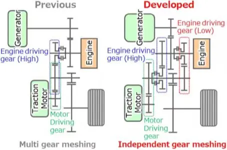
Figure 7-9 Motor drive optimization
4.3 Drag force improvement
4.3.1 The hybrid driving mode is used when going uphill or accelerating (the loss of the drive motor is large under high load and the cooling is poor at low speed, which will generate heat and reduce power output, and the thermal management requirements are very high);
4.3.2 The new system adopts two gears to achieve high driving force at low engine speed, and can achieve traction under no-load condition of the generator. The temperature of the generator coil can be reduced by up to 35%;
4.3.3 Towing can be performed in engine mode or hybrid mode, with the choice being made based on driving requirements and maximizing efficiency (in hybrid mode, if the coil is overheated, the vehicle will immediately switch to engine mode).
4.3.4 Large drive requirements can be met with two options: hybrid drive (original mode) and engine two-speed drive (new mode), which improves the driving traction and makes rational use of electrical and mechanical outputs, as shown in Figure 7-10.
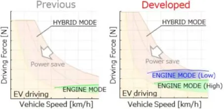
Figure 7-10 Driving drag performance optimization
5. Vehicle adaptability optimization
5.1 FDU parallel axis layout enhances adaptability
5.1.1 The motor layout of the new generation hybrid system has been greatly optimized and improved, from the original coaxial layout to a parallel axis layout, which enhances the adaptability of the axial length layout;
5.1.2 The parallel axis layout of the new generation hybrid system motor increases slightly by 4.2mm in height, but the axial length is greatly reduced, which has more layout advantages, as shown in Figure 7-11.
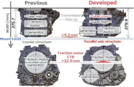
Figure 7-11 Dual motor layout optimization
Previous article:BYD solid-state battery exposed
Next article:Apple supplier TDK claims solid-state battery breakthrough
- Popular Resources
- Popular amplifiers
- A new chapter in Great Wall Motors R&D: solid-state battery technology leads the future
- Naxin Micro provides full-scenario GaN driver IC solutions
- Interpreting Huawei’s new solid-state battery patent, will it challenge CATL in 2030?
- Are pure electric/plug-in hybrid vehicles going crazy? A Chinese company has launched the world's first -40℃ dischargeable hybrid battery that is not afraid of cold
- How much do you know about intelligent driving domain control: low-end and mid-end models are accelerating their introduction, with integrated driving and parking solutions accounting for the majority
- Foresight Launches Six Advanced Stereo Sensor Suite to Revolutionize Industrial and Automotive 3D Perception
- OPTIMA launches new ORANGETOP QH6 lithium battery to adapt to extreme temperature conditions
- Allegro MicroSystems Introduces Advanced Magnetic and Inductive Position Sensing Solutions
- TDK launches second generation 6-axis IMU for automotive safety applications
- LED chemical incompatibility test to see which chemicals LEDs can be used with
- Application of ARM9 hardware coprocessor on WinCE embedded motherboard
- What are the key points for selecting rotor flowmeter?
- LM317 high power charger circuit
- A brief analysis of Embest's application and development of embedded medical devices
- Single-phase RC protection circuit
- stm32 PVD programmable voltage monitor
- Introduction and measurement of edge trigger and level trigger of 51 single chip microcomputer
- Improved design of Linux system software shell protection technology
- What to do if the ABB robot protection device stops
- CGD and Qorvo to jointly revolutionize motor control solutions
- CGD and Qorvo to jointly revolutionize motor control solutions
- Keysight Technologies FieldFox handheld analyzer with VDI spread spectrum module to achieve millimeter wave analysis function
- Infineon's PASCO2V15 XENSIV PAS CO2 5V Sensor Now Available at Mouser for Accurate CO2 Level Measurement
- Advanced gameplay, Harting takes your PCB board connection to a new level!
- Advanced gameplay, Harting takes your PCB board connection to a new level!
- A new chapter in Great Wall Motors R&D: solid-state battery technology leads the future
- Naxin Micro provides full-scenario GaN driver IC solutions
- Interpreting Huawei’s new solid-state battery patent, will it challenge CATL in 2030?
- Are pure electric/plug-in hybrid vehicles going crazy? A Chinese company has launched the world's first -40℃ dischargeable hybrid battery that is not afraid of cold
- Basic circuit design tree for RF microwave circuit engineering
- [Jihai APM32E103VET6S MINI development board review] RTC test
- Oscilloscope helps measure harmonic content calculation
- Common Linux commands in the Corelink SinA33 development board virtual machine
- Tkinter study notes——by Changjianze1
- CircuitPython 6.0.0-alpha.3 released
- 4412 development board Qt network programming-TCP implementation server and client
- [New Driving Force Technology MM32F031C6 Development Board Review] Summary Post
- What is the relationship between embedded systems and microcontrollers?
- [Automatic clock-in walking timer system based on face recognition] Unboxing (1): SiPEED Maix Bit (K210)


 LM2903DB


 京公网安备 11010802033920号