0 Introduction
The meander line structure has become a new hot spot in modern antenna design in terms of reducing antenna size and improving antenna bandwidth characteristics. In order to improve the performance of meander line antennas, researchers have proposed a variety of improved structures according to different applications and characteristics requirements, including double meander line antennas, folded meander line antennas, three-dimensional meander line antennas, gradient meander line antennas, traveling wave meander line antennas and meander line slot antennas.
This paper proposes a non-uniform meander line monopole antenna with a coupling patch on the back. The influence of the geometric dimensions of each meander line node on the antenna resonance characteristics is studied by the finite difference time domain method, and the role of the coupling patch is analyzed. Finally, a dual-band antenna with a frequency band covering IEEE 802.11b/g (2.4~2.484 GHz) and IEEE802.11a (5.15~5.35GHz, 5.725~5.825 GHz) is obtained, which can meet WLAN applications.
1 Antenna modeling and structural parameter analysis
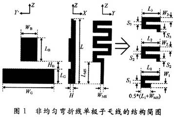
The structure of the non-uniform meander line monopole antenna is shown in Figure 1. The substrate is Rogers4350B substrate with a thickness of 0.762 mm and a relative dielectric constant of 3.48. For the convenience of analysis, the radiating element is divided into three sections; the antenna feed uses a 50 Ω microstrip line.

1.1 Effect of bending joint geometric parameters on antenna performance
The line length Ln (n=1, 2, 3) and line width Wn (n=1, 2, 3) of each bending joint are changed in turn, and the first resonant frequency f1 and the second resonant frequency f2 of the antenna are calculated. By comparing the changes in f2/f1, the regulating effect of each bending joint geometric parameter on the antenna resonance characteristics is studied.
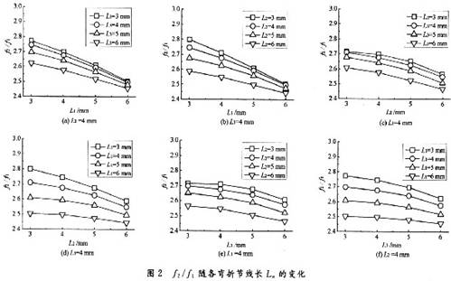
Figure 2 shows the change of antenna f2/f1 with the line length Ln of each bending joint. In Figure 2, W=58 mm, L=38 mm, LG=17 mm, HB=3 mm, S1=S2=S3=1 mm, W1=W2=W3=2mm.

Figures 2(a) to 2(f) show almost the same trend of change. As the length of the bending node line Ln increases, f2/f1 gradually decreases, and the two resonant modes approach each other. By changing the length of each bending node in the meander line antenna, the first and second resonant modes can be adjusted.
Figure 3 shows the change of antenna f2/f1 with the width of each bending node Wn. In Figure 3, W=58 mm, L=38 mm, LG=17 mm, HB=3 mm, Sl=S2=S3=1 mm, L1=L2=L3=5 mm. Compared with the change with the bending node line length Ln in Figure 2, the change of f2/f1 with the bending node line width Wn is more complicated.

Figure 3(a) shows the change of antenna f2/f1 with W1 when W2=1 mm. It can be seen that with the increase of W1, f2/f1 gradually decreases, the two resonant frequencies gradually approach each other, and almost maintain the same rate of decrease under different W3.
Figure 3(b) shows the change of antenna f2/f1 with W1 when W3=1 mm. It can be seen that with the increase of W1, f2/f1 gradually decreases, but with the increase of W2, the rate of decrease of f2/f1 gradually decreases, and finally remains almost unchanged.
Figure 3(c) shows the change of antenna f2/f1 with W2 when W1=2 mm. When W3 is small, as W2 increases, f2/f1 first shows an increasing trend; then, when W3 increases to a certain value, f2/f1 hardly changes with the change of W2; finally, as W3 continues to increase, f2/f1 shows a decreasing trend again.
Figure 3(d) shows the change of antenna f2/f1 with W2 when W3=2 mm. It can be seen that when W1 is small, f2/f1 first shows a decreasing trend; then, when W1 increases to a certain value, f2/f1 hardly changes with the change of W2; finally, as W1 continues to increase, f2/f1 shows an increasing trend again.
Figure 3(e) shows the change of antenna f2/f1 with W3 when W1=1 mm. With the increase of W3, f2/f1 gradually increases, and with the increase of W2, the increase rate of f2/f1 gradually decreases.
Figure 3(f) shows the change of antenna f2/f1 with W3 when W2=1 mm. With the increase of W3, f2/f1 gradually increases, and basically maintains the same increase rate under different W1 values.
The influence of the line width of the bend line on the antenna f2/f1 can be understood as changing the line width of the bend node changes the distribution state of the radiation current of the first and second resonant modes, and then changes the effective electrical length of the radiating element in these two modes, resulting in the change of f2/f1. The effects of W1 and W3 are just opposite. As W1 increases, f2/f1 decreases; as W3 increases, f2/f1 increases; the effect of W2 is still between W1 and W3. According to the above discussion, changing the line width of each bending node of the antenna in the meander line can adjust f2/f1.
1.2 Effect of coupling patch geometric parameters on antenna performance
Figure 4(a) shows the return loss simulation curve of the antenna when the width (WB) of the coupling patch is 5 mm, 7 mm, 9 mm, 11 mm and 13 mm respectively. The influence of the width of the coupling patch on the resonance performance of the antenna is mainly concentrated in the high frequency band. As the width of the coupling patch increases, the resonant mode matching characteristics generated by the coupling patch become better, and the intrinsic high-order mode moves to low frequency and gradually disappears.

Figure 4(b) shows the return loss simulation curve of the antenna when the length of the coupling patch (LB) is 7 mm, 9 mm, 11 mm, 13 mm and 15 mm respectively. As the length of the coupling patch increases, the lowest resonant mode of the antenna moves to the low frequency, and the matching characteristics become better, but the impedance bandwidth decreases. For the high frequency band, when the value of LB is less than 9 mm, the resonant mode generated by the coupling patch does not appear. The reason for this may be that the resonant mode generated by the coupling patch coincides with the intrinsic high-order mode. As LB continues to increase, the resonant mode generated by the coupling patch appears and moves to the low frequency direction, and the two modes in the high frequency band gradually move away.
Figure 4(c) shows the return loss simulation curve of the antenna when the height of the coupling patch from the ground plane (HB) is 1 mm, 2 mm, 3 mm, 4 mm and 5 mm respectively. It can be seen from the figure that all resonant modes move to the low frequency direction. When the height of the coupling patch from the ground plane is between 2 and 3 m, two resonant modes appear in the high frequency band; as the height of the coupling patch from the ground plane continues to increase, the two resonant modes in the high frequency band move away, and the matching characteristics deteriorate.
From the above discussion, it can be concluded that the influence of the coupling patch on the antenna performance is mainly concentrated in the high frequency band. Reasonable selection of the geometric dimensions of the coupling patch and the height from the ground plane can improve the matching characteristics of the second resonant mode and expand the impedance bandwidth without affecting the first resonant mode of the antenna.
2 Actual test results of the antenna
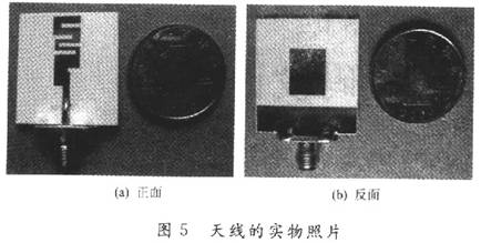
Based on comprehensive consideration of the impedance bandwidth and radiation characteristics, the following optimized antenna geometric parameters are obtained, where L=29 mm, L1=6 mm, L2=6 mm, L3=6.5 mm, W1=3 mm, W2=1 mm, W3=2.5 mm, S1=S2=S3=1 mm, LB=11 mm, WB=9 mm, WG=26 mm, HB=3 mm, LG=7 mm, LMS=10 mm. The actual antenna is shown in Figure 5.


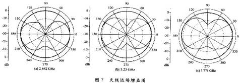
Figure 6 shows the return loss curve of the non-uniform meander line monopole antenna. It can be seen from the figure that the simulation results are consistent with the actual test results. The impedance bandwidth measured in the low frequency band (S1-1 <-10 dB) is about 0.5 GHz (2.2 ~ 2.7 GHz); the impedance bandwidth actually measured in the high frequency band (S11 <-10 dB) is about 1.8 GHz (4.48 ~ 6.28 GHz). Figures 7 (a) to (c) show the gain diagrams of the non-uniform meander line monopole antenna at 2.442 GHz, 5.25 GHz and 5.775 GHz, respectively, with gains of 0.7 dBi, 1.65 dBi and 2.3 dBi, respectively.

3 Conclusion
A planar non-uniform meander line monopole antenna with a coupling patch on the back is proposed. The relative positions of the first and second resonant frequencies in the meander line antenna are adjusted by changing the geometric dimensions of each bending node of the meander line to achieve the purpose of dual-frequency adjustment. The resonant characteristics of the higher-order resonant mode of the meander line antenna are improved by the back coupling patch. Finally, a dual-frequency meander line monopole antenna covering the frequency band of IEEE 802.11b/g (2.4~2.48 GHz) and IEEE 802.11a (5.15~5.35GHz, 5.725~5.825 GHz) is designed. The gains at 2.442 GHz, 5.25 GHz and 5.775 GHz are 0.7 dBi, 1.65 dBi and 2.3 dBi respectively, which can meet the WLAN application.
Previous article:RF PA Allocation Design Based on Complex Plane Circular Graph
Next article:Utilizes 16-bit DAC to provide 40-channel output with programmable
- High signal-to-noise ratio MEMS microphone drives artificial intelligence interaction
- Advantages of using a differential-to-single-ended RF amplifier in a transmit signal chain design
- ON Semiconductor CEO Appears at Munich Electronica Show and Launches Treo Platform
- ON Semiconductor Launches Industry-Leading Analog and Mixed-Signal Platform
- Analog Devices ADAQ7767-1 μModule DAQ Solution for Rapid Development of Precision Data Acquisition Systems Now Available at Mouser
- Domestic high-precision, high-speed ADC chips are on the rise
- Microcontrollers that combine Hi-Fi, intelligence and USB multi-channel features – ushering in a new era of digital audio
- Using capacitive PGA, Naxin Micro launches high-precision multi-channel 24/16-bit Δ-Σ ADC
- Fully Differential Amplifier Provides High Voltage, Low Noise Signals for Precision Data Acquisition Signal Chain
- Innolux's intelligent steer-by-wire solution makes cars smarter and safer
- 8051 MCU - Parity Check
- How to efficiently balance the sensitivity of tactile sensing interfaces
- What should I do if the servo motor shakes? What causes the servo motor to shake quickly?
- 【Brushless Motor】Analysis of three-phase BLDC motor and sharing of two popular development boards
- Midea Industrial Technology's subsidiaries Clou Electronics and Hekang New Energy jointly appeared at the Munich Battery Energy Storage Exhibition and Solar Energy Exhibition
- Guoxin Sichen | Application of ferroelectric memory PB85RS2MC in power battery management, with a capacity of 2M
- Analysis of common faults of frequency converter
- In a head-on competition with Qualcomm, what kind of cockpit products has Intel come up with?
- Dalian Rongke's all-vanadium liquid flow battery energy storage equipment industrialization project has entered the sprint stage before production
- Allegro MicroSystems Introduces Advanced Magnetic and Inductive Position Sensing Solutions at Electronica 2024
- Car key in the left hand, liveness detection radar in the right hand, UWB is imperative for cars!
- After a decade of rapid development, domestic CIS has entered the market
- Aegis Dagger Battery + Thor EM-i Super Hybrid, Geely New Energy has thrown out two "king bombs"
- A brief discussion on functional safety - fault, error, and failure
- In the smart car 2.0 cycle, these core industry chains are facing major opportunities!
- The United States and Japan are developing new batteries. CATL faces challenges? How should China's new energy battery industry respond?
- Murata launches high-precision 6-axis inertial sensor for automobiles
- Ford patents pre-charge alarm to help save costs and respond to emergencies
- New real-time microcontroller system from Texas Instruments enables smarter processing in automotive and industrial applications
- Live broadcast with prizes | Infineon BMS solutions protect electric vehicles and energy storage systems!
- [Qinheng RISC-V core CH582] PWM control heater
- Kicad one-click gerber generation plug-in
- EEWORLD University Hall----Easy simulation and control of quadcopters with MATLAB & Simulink
- Now in mass production! Infineon's carbon dioxide sensor based on photoacoustic spectroscopy (PAS) technology gives objects the sense of smell
- EEWORLD University Hall----MIT Open Course: Circuits and Electronics
- Please analyze the circuit at the output end of the power supply.
- What are forward and flyback power supplies? What are the differences between forward and flyback? How to quickly distinguish them?
- Brief Introduction of Push-Pull Circuit
- CPU card program terminal sends data to ESAM

 A portable ECG for recording and flexible development of algorithms and stress detection
 BLE directional antenna application


 京公网安备 11010802033920号