Screws are one of the most important fasteners in modern industry and are in great demand. For different hole diameters, the matching of screws and nuts is particularly critical. Minor differences in precision equipment may cause system problems in transmission and electric devices. Therefore, the development of drilling and tapping technology has been quickly put on the agenda.
The earliest threaded hole inspection was done manually, that is, the operator screwed the bolt or gauge into the hole for inspection. However, the manual method was gradually replaced by automated inspection methods due to problems such as high labor intensity and high cost. The one studied here is the fine inspection of metal screw holes using advanced sensors.
1 Basic Concepts of Inductive Sensors
1.1 Basic structure and sensitivity
The excitation element of the inductive sensor consists of a coil and a ferrite core (see Figure 1). Formula (1) is the mathematical model of the inductive sensor.

Where: L is the inductance; N is the number of turns of the coil; L is the air gap permeability; S is the air gap cross-sectional area; D is the air gap thickness.
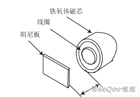
Figure 1 Basic components of an inductive sensor
From formula (1), we can know that the coil inductance L is inversely proportional to the air gap thickness D and proportional to the air gap cross-sectional area S. Assuming that the air gap at the starting position is D0, the corresponding initial inductance is L0, and S is fixed, when D changes slightly to $D, the change in self-inductance dL is (ignoring higher-order terms):
1.2 Working principle
Inductive sensors are based on electromagnetic field theory. They use the change in magnetic resistance of the measured magnetic circuit to cause the change in the self-inductance or mutual inductance of the sensor coil, thereby causing the change in the coil inductance to achieve non-electrical quantity measurement.
When an alternating current passes through the coil, the coil generates an alternating magnetic field, which passes through the iron core and points to one side of the iron core, that is, the excitation end of the sensor. When a metal object or a magnetic object approaches the excitation end of the sensor, the magnetic field will be deformed. The magnetic field state diagram can be obtained by computer simulation (see Figure 2). As can be seen from Figure 2, the magnetic field effect when a conductive material (such as a steel plate) approaches the excitation end, the changing magnetic field causes the impedance of the sensor coil to change. The circuit integrated in the sensor measures the change in coil impedance and converts it into a switch signal output. Figure 3 shows its detection flow chart.
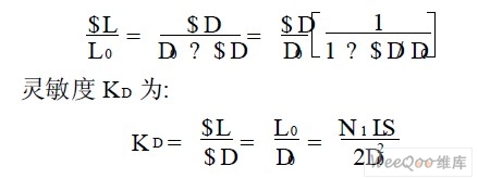
Figure 2 Magnetic field state diagram
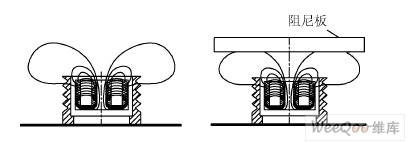
Figure 2 Magnetic field state diagram
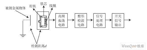
Figure 3 Detection flow chart
2 System Block Diagram Design
According to the basic concept of inductive sensors, combined with the content and requirements of this paper, the block diagram of the automatic detection system based on inductive sensors was designed, as shown in Figure 4.

Figure 4 Block diagram of automatic detection system based on inductive sensor
3 Hardware Circuit Design
The design uses the experimental specimen St37 (steel 40 mm wide) provided by Bosch, Germany, to make measurement marks and serve as the standard material to be tested. When the material specimen contacts the sensor, the ultrasonic distance sensor measuring device will display a reference value. By changing the distance between the specimen and the excitation end of the inductive sensor, the magnitude of its output current is measured to determine the detectable range of the sensor. The analog inductive sensor IA outputs an analog signal proportional to the distance between the sensors when the distance between the damping plate and the sensor is determined.
This paper uses the signal conditioning circuit with ultrasonic sensor and the ammeter display to determine the relationship between the system input signal and the output signal. From this, the linear detection area of the analog output inductive sensor is obtained. Figure 5 is the detection wiring diagram (the red connection is the positive polarity equipotential point of the power supply, and the blue connection is the negative polarity equipotential point of the power supply).
4 Threaded hole diameter identification application
The output current value of the inductive analog output sensor depends on the distance between the sensor and the metal object being measured. The detection of mounting screw holes of different diameters on metal plates is an important application case, as shown in Figure 6.
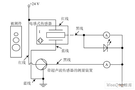
Figure 5 Detection connection diagram
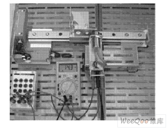
Figure 6 Threaded hole diameter detection application case
In Figure 6, an aluminum plate (80 mm @80 mm) with three mounting screw holes is used as the workpiece to be measured. The aluminum plate is mounted on the non-rotating specimen bracket and parallel to the bracket rail. The height compensator is installed parallel to the rail at a distance of 4 mm from the rail. The inductor analog output sensor is installed on the height compensator. Since the linear measurement range of the analog inductor sensor has been determined before, the ammeter is not connected to the ultrasonic sensor at this time, but to the inductive sensor.
Align the 6 mm circular hole to the center of the sensor, and place the adjacent 12 mm circular hole outside the sensor's detection range (this requirement also applies to the distance between metal materials on the conveyor belt during enterprise detection). Move the 12 mm and 15 mm circular holes to the center of the sensor excitation end in turn, and ensure that the adjacent circular holes will not be detected. Record the measured current values as shown in Table 1.
5 Data analysis and processing
The measured data were fitted, as shown in Figure 7.
As shown in Figure 7, for this inductive analog output sensor, between 3 mm and 10 mm, the current changes from 0 mA to 25 mA, and the distance and current are linearly related; beyond this range, the distance and current are nonlinearly related, and within this range (3~10 mm), the inductive analog output sensor will not produce hysteresis. Therefore, the inductive analog output sensor is suitable for measuring the distance of specified materials.
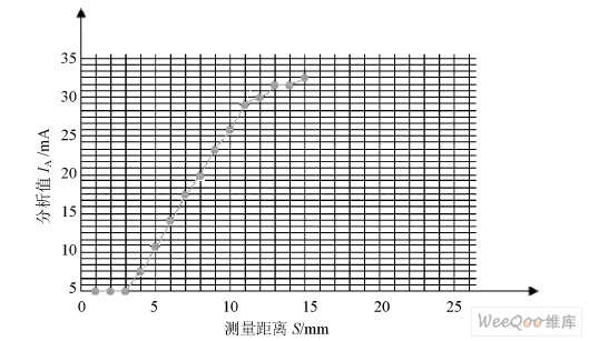
Figure 7. Analog inductor current path characteristic curve fitting

6 Conclusion
The analog inductive sensor can provide a current or voltage signal proportional to the displacement of the object. Through different measurement current or voltage values, the size of the circular hole diameter can be estimated. In actual measurement, the lateral accuracy is related to the diameter size and material of the circular hole. If the diameter of the circular hole is smaller, the attenuation of the analog inductive sensor output is greater, and the detection of small differences in threaded hole diameter is relatively accurate. Of course, for circular hole materials, the conversion factor of aluminum material is 0.42, while the conversion factor of high-grade steel is 0.72. The conversion factor of aluminum material is relatively small, so the use of materials with high conversion factors will increase the sensitivity of this test system, so as to complete reliable detection and control tasks.
Previous article:Design of Compensation Regulator Temperature Drift Based on DS1859 and MAX604
Next article:Analysis of key design points of high-performance and low-power solar scale SoC
- High signal-to-noise ratio MEMS microphone drives artificial intelligence interaction
- Advantages of using a differential-to-single-ended RF amplifier in a transmit signal chain design
- ON Semiconductor CEO Appears at Munich Electronica Show and Launches Treo Platform
- ON Semiconductor Launches Industry-Leading Analog and Mixed-Signal Platform
- Analog Devices ADAQ7767-1 μModule DAQ Solution for Rapid Development of Precision Data Acquisition Systems Now Available at Mouser
- Domestic high-precision, high-speed ADC chips are on the rise
- Microcontrollers that combine Hi-Fi, intelligence and USB multi-channel features – ushering in a new era of digital audio
- Using capacitive PGA, Naxin Micro launches high-precision multi-channel 24/16-bit Δ-Σ ADC
- Fully Differential Amplifier Provides High Voltage, Low Noise Signals for Precision Data Acquisition Signal Chain
- Innolux's intelligent steer-by-wire solution makes cars smarter and safer
- 8051 MCU - Parity Check
- How to efficiently balance the sensitivity of tactile sensing interfaces
- What should I do if the servo motor shakes? What causes the servo motor to shake quickly?
- 【Brushless Motor】Analysis of three-phase BLDC motor and sharing of two popular development boards
- Midea Industrial Technology's subsidiaries Clou Electronics and Hekang New Energy jointly appeared at the Munich Battery Energy Storage Exhibition and Solar Energy Exhibition
- Guoxin Sichen | Application of ferroelectric memory PB85RS2MC in power battery management, with a capacity of 2M
- Analysis of common faults of frequency converter
- In a head-on competition with Qualcomm, what kind of cockpit products has Intel come up with?
- Dalian Rongke's all-vanadium liquid flow battery energy storage equipment industrialization project has entered the sprint stage before production
- Allegro MicroSystems Introduces Advanced Magnetic and Inductive Position Sensing Solutions at Electronica 2024
- Car key in the left hand, liveness detection radar in the right hand, UWB is imperative for cars!
- After a decade of rapid development, domestic CIS has entered the market
- Aegis Dagger Battery + Thor EM-i Super Hybrid, Geely New Energy has thrown out two "king bombs"
- A brief discussion on functional safety - fault, error, and failure
- In the smart car 2.0 cycle, these core industry chains are facing major opportunities!
- The United States and Japan are developing new batteries. CATL faces challenges? How should China's new energy battery industry respond?
- Murata launches high-precision 6-axis inertial sensor for automobiles
- Ford patents pre-charge alarm to help save costs and respond to emergencies
- New real-time microcontroller system from Texas Instruments enables smarter processing in automotive and industrial applications
- [ModelSim FAQ] Can't launch the ModelSim-Altera software
- Please give me some advice!!!
- Can the vehicle gateway be integrated into other modules?
- How to select MOS tubes for three-phase full-bridge inverter drive circuits?
- [RT-Thread Reading Notes] Part 2 (4) Events, Software Timers, Memory Management
- RK3399 delete the boot lock screen interface
- Let's talk about DSP audio processing
- CPU card programming process
- Blind guess: How does the ESP32 “Piranha Plant” design achieve the opening and closing of its petals?
- The calculation problem of frequency count value

 New Concept Analog Circuit 1-Transistor [Text Version] (Yang Jianguo)


 京公网安备 11010802033920号