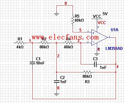
Third-order RC active low-pass filter circuit diagram
The calculation formula is cut-off frequency F=1/(WR1C1), R1=R4=2R2=2R3, C1=10C.
Previous article:Second-order active low-pass filter circuit diagram
Next article:Active filter circuit diagram
- Popular Resources
- Popular amplifiers
Recommended Content
Latest Analog Electronics Articles
- High signal-to-noise ratio MEMS microphone drives artificial intelligence interaction
- Advantages of using a differential-to-single-ended RF amplifier in a transmit signal chain design
- ON Semiconductor CEO Appears at Munich Electronica Show and Launches Treo Platform
- ON Semiconductor Launches Industry-Leading Analog and Mixed-Signal Platform
- Analog Devices ADAQ7767-1 μModule DAQ Solution for Rapid Development of Precision Data Acquisition Systems Now Available at Mouser
- Domestic high-precision, high-speed ADC chips are on the rise
- Microcontrollers that combine Hi-Fi, intelligence and USB multi-channel features – ushering in a new era of digital audio
- Using capacitive PGA, Naxin Micro launches high-precision multi-channel 24/16-bit Δ-Σ ADC
- Fully Differential Amplifier Provides High Voltage, Low Noise Signals for Precision Data Acquisition Signal Chain
MoreSelected Circuit Diagrams
MorePopular Articles
- LED chemical incompatibility test to see which chemicals LEDs can be used with
- Application of ARM9 hardware coprocessor on WinCE embedded motherboard
- What are the key points for selecting rotor flowmeter?
- LM317 high power charger circuit
- A brief analysis of Embest's application and development of embedded medical devices
- Single-phase RC protection circuit
- stm32 PVD programmable voltage monitor
- Introduction and measurement of edge trigger and level trigger of 51 single chip microcomputer
- Improved design of Linux system software shell protection technology
- What to do if the ABB robot protection device stops
MoreDaily News
- ASML predicts that its revenue in 2030 will exceed 457 billion yuan! Gross profit margin 56-60%
- Detailed explanation of intelligent car body perception system
- How to solve the problem that the servo drive is not enabled
- Why does the servo drive not power on?
- What point should I connect to when the servo is turned on?
- How to turn on the internal enable of Panasonic servo drive?
- What is the rigidity setting of Panasonic servo drive?
- How to change the inertia ratio of Panasonic servo drive
- What is the inertia ratio of the servo motor?
- Is it better for the motor to have a large or small moment of inertia?
Guess you like
- PCB drawing board suggestions for B628 lithium battery boost circuit chip
- RT Thread IPC Summary
- Offline voice control solution
- What is the working principle of pneumatic solenoid valve? What are the classifications of pneumatic solenoid valves?
- [SC8905 EVM Evaluation] + I2C communication between MCU and SC8905
- Application of Mir MYC-YA15XC-T core board in LoRa smart gateway
- Spectrum Analysis Series: 1dB Gain Compression Point Overview and Testing
- FPGA Tutorial Series
- [RVB2601 Creative Application Development] 2 Familiar with basic peripherals GPIO
- [2022 Digi-Key Innovation Design Competition] Deploy blockchain smart contracts

 LTC6363HDCB#TRMPBF


 京公网安备 11010802033920号