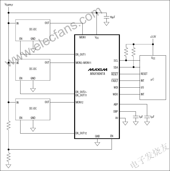
The MAX16047A /MAX16049A EEPROM -configurable system managers monitor, sequence, and track multiple system voltages. The MAX16047A can manage 12 system voltages simultaneously, and the MAX16049A can manage 8 supply voltages. The devices integrate analog-to-digital converters (ADCs) for monitoring supply voltages and configurable outputs for sequencing and tracking supplies (at power-up and power-down). Nonvolatile EEPROM registers can be configured to record upper and lower voltage limits, set timing and sequencing as required, and store critical fault data so that fault information can be read back after a fault occurs.
The internal 1% accurate 10-bit ADC measures each input and compares the result with the upper and lower voltage thresholds and a voltage that can be configured as an upper or lower limit. When the detected voltage exceeds the set threshold, a fault alarm signal is generated. Three independent alarm outputs can be configured for different fault conditions.
The integrated sequencer/tracker ensures accurate control of 12 (MAX16047A) or 8 (MAX16049A) power inputs during power-up and power-down. Four channels (EN_OUT1–EN_OUT4) use external series MOSFETs for closed-loop tracking, while six outputs (EN_OUT1–EN_OUT6) drive MOSFETs directly with the charge pump output without closed-loop tracking.
The MAX16047A/MAX16049A provide six programmable general-purpose input/output pins (GPIOs). In addition to being used as EEPROM-configurable I/O pins, these GPIOs can also be used as dedicated fault outputs, watchdog inputs or outputs (WDI/WDO), or manual resets (active-low MR).
The MAX16047A/MAX16049A have two fault management methods for recording information when critical fault conditions occur in the system. The fault log records the fault in the internal EEPROM. To prevent accidental erase operations, a latch bit can be set to protect the stored fault data.
The MAX16047A/MAX16049A are configured using either the I²C/SMBus™ or JTAG serial interface. The devices are available in a 56-pin, 8mm x 8mm TQFN package and are specified over the -40°C to +125°C temperature range.
Key Features
Operating voltage range from 3V to 14V
1% accurate 10-bit ADC for monitoring 12/8 inputs
12/8 monitoring inputs with 1 overvoltage threshold/1 undervoltage threshold/1 selectable threshold
Non-volatile fault event recorder
Power-on and power-off sequencing
12/8-way sequencing/power-good indication output
Up to four closed-loop tracking
Two programmable fault outputs and one reset output
Six general purpose input/outputs configurable as:
Dedicated fault output
Watchdog timer function
Manual reset
I²C/SMBus and JTAG interfaces
Delay and threshold configuration via EEPROM
100 bytes internal user EEPROM
56-pin (8mm x 8mm) TQFN package
-40°C to +125°C operating temperature range

Previous article:Using PSoC I/O Analog Multiplexers to Simplify Sensor Control Design
Next article:MPEG-4 shape error concealment technology based on frequency domain watermark embedding method
- Popular Resources
- Popular amplifiers
- High signal-to-noise ratio MEMS microphone drives artificial intelligence interaction
- Advantages of using a differential-to-single-ended RF amplifier in a transmit signal chain design
- ON Semiconductor CEO Appears at Munich Electronica Show and Launches Treo Platform
- ON Semiconductor Launches Industry-Leading Analog and Mixed-Signal Platform
- Analog Devices ADAQ7767-1 μModule DAQ Solution for Rapid Development of Precision Data Acquisition Systems Now Available at Mouser
- Domestic high-precision, high-speed ADC chips are on the rise
- Microcontrollers that combine Hi-Fi, intelligence and USB multi-channel features – ushering in a new era of digital audio
- Using capacitive PGA, Naxin Micro launches high-precision multi-channel 24/16-bit Δ-Σ ADC
- Fully Differential Amplifier Provides High Voltage, Low Noise Signals for Precision Data Acquisition Signal Chain
- LED chemical incompatibility test to see which chemicals LEDs can be used with
- Application of ARM9 hardware coprocessor on WinCE embedded motherboard
- What are the key points for selecting rotor flowmeter?
- LM317 high power charger circuit
- A brief analysis of Embest's application and development of embedded medical devices
- Single-phase RC protection circuit
- stm32 PVD programmable voltage monitor
- Introduction and measurement of edge trigger and level trigger of 51 single chip microcomputer
- Improved design of Linux system software shell protection technology
- What to do if the ABB robot protection device stops
- CGD and Qorvo to jointly revolutionize motor control solutions
- CGD and Qorvo to jointly revolutionize motor control solutions
- Keysight Technologies FieldFox handheld analyzer with VDI spread spectrum module to achieve millimeter wave analysis function
- Infineon's PASCO2V15 XENSIV PAS CO2 5V Sensor Now Available at Mouser for Accurate CO2 Level Measurement
- Advanced gameplay, Harting takes your PCB board connection to a new level!
- Advanced gameplay, Harting takes your PCB board connection to a new level!
- A new chapter in Great Wall Motors R&D: solid-state battery technology leads the future
- Naxin Micro provides full-scenario GaN driver IC solutions
- Interpreting Huawei’s new solid-state battery patent, will it challenge CATL in 2030?
- Are pure electric/plug-in hybrid vehicles going crazy? A Chinese company has launched the world's first -40℃ dischargeable hybrid battery that is not afraid of cold
- Is it true that the greater the memory depth of an oscilloscope, the better?
- Comprehensive understanding of antennas, the knowledge you don’t know!
- Interrupt service program writing rules
- Help! UC2842 flyback power supply output problem
- Vicor engineers invite you to talk about efficient power supply
- What material is the magnetic ring made of? Just look at the color!
- Sinlinx A33 development board boa and CGI transplantation
- Making a CPU out of a bunch of switches?
- [TI recommended course] #Amplifier design in test and measurement#
- Problems with using printf to print floating point numbers in a single chip microcomputer

 MAX4250AAUK


 京公网安备 11010802033920号