1. Introduction
The main factor affecting the reliability of the electrical system is the input and output part of the PLC interface. We used PLC soft components in the transformation of the horizontal lathe, reasonably designed the control program, and improved the reliability of the system.
2. Main factors affecting the reliability of PLC electrical system
The PLC control system can be simply divided into three parts: the signaling element (input part), the memory network (program part) and the electrical actuator (output part). For systems controlled by relays, the main factor affecting the reliability of the system is the memory network composed of intermediate relays. For PLC control systems, the high-reliability PLC replaces the memory network composed of intermediate relays, overcomes the inherent defects of low reliability of mechanical action intermediate relays, and greatly improves the reliability of the system. At this time, the reliability of the "signaling element" and "electrical actuator" connected to the input and output of the PLC itself has become the main factor affecting the reliability of the entire electrical system. While improving the reliability of the "signaling element" and "electrical actuator", the safety of the PLC is also improved. There are usually two methods: one is to select high-quality components; the other is to perform status detection and fault diagnosis on these components with higher failure rates, but both are affected by hardware conditions and economic conditions and limit the scope of application.
PLC has a variety of soft components (such as internal timers, counters, auxiliary relays, etc.), so it can be used to design some programs to shield the false signals of input components and prevent the malfunction of output components. The most practical methods are (1) using software and hardware interlocking design to prevent false signals and malfunctions; (2) improving the reliability of wiring at the input and output ends to improve the safety of PLC. This article takes the transformation of a horizontal cone bed as an example to introduce the design method of using PLC soft components to improve system reliability.
3. Use PLC soft component design to transform the horizontal bed and improve system reliability

3.1 Introduction to the working principle of horizontal milling machine
The ladder diagram is designed based on the original relay circuit diagram. This method does not change the external characteristics of the system, but overcomes the low reliability of the mechanical action intermediate relay. For operators, in addition to the improved reliability of the control system, there is no difference between the system before and after the transformation, and they do not need to change the long-term operating habits. This design method generally does not require changes to the control panel and its components, so it can reduce the cost and workload of hardware transformation.
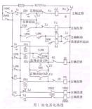
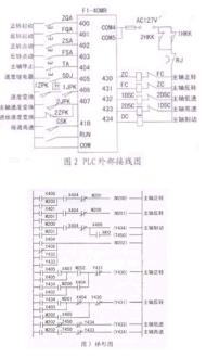
Figure 1 is the relay control circuit diagram of the horizontal hammer machine, and Figures 2 and 3 are the external wiring diagram and ladder diagram of the PLC control system that realizes the same function. The spindle motor of the horizontal hammer machine is a dual-speed asynchronous motor. The intermediate relays ZC and FC control the start and stop of the spindle motor. The contactors ZC and FC control the forward and reverse rotation of the spindle motor. The contactors 1DSC, 2DSC and the time relay SJ control the speed change of the spindle motor. The contactor DC is used to short-circuit the brake resistor in series in the stator circuit. 1JPK, 2JPK and 1ZPK, 2ZPK are the limit switches on the speed control panel, and 1HKK, 2HKK are the limit switches for the interlocking of the spindle feed and the movement of the worktable.
3.2 Design ET-made horizontal lathe with PLC software and hardware interlocking to improve system reliability
In the relay circuit that controls the forward and reverse rotation of the spindle motor, in order to prevent the two contactors (such as ZC and FC in Figure 1) that control the forward and reverse rotation from operating at the same time and causing a short circuit in the three-phase power supply, an interlocking circuit is set up, that is, the normally closed contact of one of the two contactors is connected in series with the coil of another contactor. The corresponding interlocking circuit is also set up in the ladder diagram, but the interlocking circuit in the ladder diagram can only ensure that the two corresponding hardware relays on the PLC output module do not operate at the same time. If the main circuit current is too large or the contactor quality is poor, the main contacts of one of the two contactors are disconnected from the main circuit and the arc welding is generated, and the main contacts are still connected after the power is cut off, if the power is on in the other contactor, it will still cause a short circuit accident in the two-phase power supply.
To prevent this situation, an interlocking circuit should be set outside the PLC (see Figure 1). Assume that the main contact of contactor ZC is welded by arc. At this time, the auxiliary normally closed contact of ZC connected in series with the FC line country is disconnected, so the FC line country cannot be energized.
3.3 Use PLC auxiliary relay to simplify the circuit and improve the reliability of the electrical system
In Figure 1, ZC, FC, lDSC, and 2DSC are all controlled by the contact parallel circuit of TA, lZPK, lJPK, ZC, and FC. In order to simplify the circuit, an auxiliary relay M202 controlled by the above parallel circuit is set in the ladder diagram, which is similar to the intermediate relay in the relay circuit.
In addition, there are methods to improve the reliability of PLC control systems, such as: (l) When inductive components are connected to the input and output terminals, a resistor-capacitor circuit should be connected in parallel at both ends to control the impact of the arc generated when the circuit is disconnected on the PLC. The resistor can be 51~12OQ, and the capacitor can be 0.1~0.47μF. The rated voltage of the capacitor should be greater than the peak voltage of the power supply.
(2) The PLC control cabinet is installed in a room without high voltage, high current and strong radiation.
(3) Use an isolation transformer and power it with a single-circuit twisted pair cable.

4. Conclusion
The method of using PLC to improve system reliability is economical and practical. It has been successfully applied in the PLC control system of horizontal boring machines, realizing equipment transformation and production process automation, improving labor productivity, improving enterprise management, and increasing enterprise economic benefits.
Previous article:Low-cost and high-reliability applications of high-brightness fiber-coupled output semiconductor lasers
Next article:Electrothermal Modeling and Reliability Prediction of Electronic Components (I)
Recommended ReadingLatest update time:2024-11-15 15:46


- Popular Resources
- Popular amplifiers
- High signal-to-noise ratio MEMS microphone drives artificial intelligence interaction
- Advantages of using a differential-to-single-ended RF amplifier in a transmit signal chain design
- ON Semiconductor CEO Appears at Munich Electronica Show and Launches Treo Platform
- ON Semiconductor Launches Industry-Leading Analog and Mixed-Signal Platform
- Analog Devices ADAQ7767-1 μModule DAQ Solution for Rapid Development of Precision Data Acquisition Systems Now Available at Mouser
- Domestic high-precision, high-speed ADC chips are on the rise
- Microcontrollers that combine Hi-Fi, intelligence and USB multi-channel features – ushering in a new era of digital audio
- Using capacitive PGA, Naxin Micro launches high-precision multi-channel 24/16-bit Δ-Σ ADC
- Fully Differential Amplifier Provides High Voltage, Low Noise Signals for Precision Data Acquisition Signal Chain
- LED chemical incompatibility test to see which chemicals LEDs can be used with
- Application of ARM9 hardware coprocessor on WinCE embedded motherboard
- What are the key points for selecting rotor flowmeter?
- LM317 high power charger circuit
- A brief analysis of Embest's application and development of embedded medical devices
- Single-phase RC protection circuit
- stm32 PVD programmable voltage monitor
- Introduction and measurement of edge trigger and level trigger of 51 single chip microcomputer
- Improved design of Linux system software shell protection technology
- What to do if the ABB robot protection device stops
- Huawei's Strategic Department Director Gai Gang: The cumulative installed base of open source Euler operating system exceeds 10 million sets
- Download from the Internet--ARM Getting Started Notes
- Learn ARM development(22)
- Learn ARM development(21)
- Learn ARM development(20)
- Learn ARM development(19)
- Learn ARM development(14)
- Learn ARM development(15)
- Analysis of the application of several common contact parts in high-voltage connectors of new energy vehicles
- Wiring harness durability test and contact voltage drop test method
- OPPO lays off 20% of its employees?
- [Allwinner V853 heterogeneous multi-core AI intelligent vision development board review] Simple unboxing
- C6000 Program Optimization Process and Method
- CCS5.5.0 compilation problem: "different version of compiler"
- PSRAM Usage Instructions for GW1NR-9K
- SiC market is growing rapidly
- [Sipeed LicheeRV 86 Panel Review] Homemade CKLink-lite debugger, debugging D1 bare metal programming
- "Analog input signal" protection circuit
- Simple---a TMS320F28035 key driver
- Reference Design for EtherCAT Slave without DDR

 Siemens PLC Programming Technology and Application Cases (Edited by Liu Zhenquan, Wang Hanzhi, Yang Kun, etc.)


 京公网安备 11010802033920号