The three-axis acceleration sensor MMA7260Q can measure the inertia of the smart car, select the best center of gravity, and accurately locate the smart car in a straight line, curve, ramp, drift and other running states; the acceleration sensor can predict the path in advance and determine when the braking effect is best. It also solves the balance and direction recognition of the upright walking car model.
Therefore, a design based on three-axis acceleration sensor in smart car control and path recognition is proposed. This design uses three-axis acceleration sensor MMA7260Q to measure the acceleration signal of the smart car in motion, and uses embedded single chip MC9S12XSl28B as the core controller to sample the acceleration signal, A/D conversion, and then store the characteristic data in EEPROM. It solves the problem of smart car motion path analysis and obtains the car acceleration in real time, so as to obtain the running status of the car more comprehensively, which provides the possibility for smooth control and better road condition recognition.
In the upright walking car model, applying the same principle and selecting the optimal center of gravity can effectively solve the balance and direction recognition of the upright walking car model, thereby speeding up the driving speed of the car model.
The experimental results prove that the acceleration sensor has strong anti-interference ability and can extract angle information more accurately, ensuring that the smart car can travel at a higher speed on a straight road and can turn smoothly on a curve without stalling.
1. Existing problems of smart cars
During the operation of the car model, people cannot judge the running state of the car. Using an acceleration sensor to monitor the acceleration of the car can more accurately know the running state of the car, and can distinguish between ramps and non-ramp roads by detecting the change of acceleration in a certain direction. So as to make corresponding strategic responses. Avoid the car from stopping and overturning during the competition. And it also solves the balance of the upright walking car model during the walking process.
2. MMA7260Q Introduction
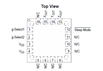
The accelerometer is MMA7260Q produced by Freescale.

Figure 1 Chip pin definition
2.1 Features of MMA7260Q:
It provides three-axis XYZ detection sensitivity in one device, with optional sensitivity: 1.5g, 2g, 4g and 6g; low power consumption, sleep mode, low voltage operation generally at 2.2V~3.6V, fast startup, generally startup time is 1ms; it has low noise, and the package is generally a 16-pin 6mm x 6mm x 1.45mm pinless quad flat package (QFN).
2.2 Advantages of MMA7260Q
Provides flexible optional ranges for multi-functional applications: including 1.5g, 2g, 4g and 6g; low power consumption, which can extend battery life Short power-on response time, best suited for sleep mode of battery-powered handheld devices, small number of components - saving cost and space Low noise, high sensitivity, with adaptive function, high frequency and resolution, providing accurate fall, tilt, move, place, vibration and swing sensing sensitivity Recommended gravity acceleration levels for different applications Free fall detection: 1g~2g Tilt control: 1g~2g.
2.3 Analysis of Acceleration Sensor Applications
2.3.1 Analysis of interference factors
The chip can test the acceleration change in one direction. Therefore, different installation methods are adopted, and more interference factors must be considered during the process.
1. Mechanical vibration of the vehicle during movement
2. The impact of uneven speed control on the vehicle's motion state
3. The difference between the error under normal circumstances and the output generated by the acceleration sensor under normal circumstances
2.3.2 Installation method analysis
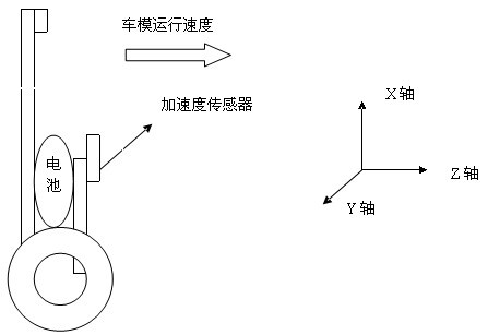
If it is installed on the pole where the camera is installed, the pole will shake left and right when the car accelerates or decelerates. Through Labview observation, it is found that the interference is too large. If it is installed at the rear of the car, the impact on MEMS will be more obvious than before due to the vibration of the motor itself.
After testing, it is found that if the acceleration in the horizontal X direction is measured, the circuit board with MMA2260 should be mounted on the front of the vehicle.

Figure 2 Acceleration sensor installation method
If it is installed on an upright walking car model, the acceleration in the vertical Z direction should be measured.

Figure 3 Schematic diagram of upright walking car model installation
Previous article:Four major storage technologies: their advantages and disadvantages
Next article:Application of triaxial acceleration sensor in intelligent vehicle control and road recognition (Part 2)
- Popular Resources
- Popular amplifiers
- High signal-to-noise ratio MEMS microphone drives artificial intelligence interaction
- Advantages of using a differential-to-single-ended RF amplifier in a transmit signal chain design
- ON Semiconductor CEO Appears at Munich Electronica Show and Launches Treo Platform
- ON Semiconductor Launches Industry-Leading Analog and Mixed-Signal Platform
- Analog Devices ADAQ7767-1 μModule DAQ Solution for Rapid Development of Precision Data Acquisition Systems Now Available at Mouser
- Domestic high-precision, high-speed ADC chips are on the rise
- Microcontrollers that combine Hi-Fi, intelligence and USB multi-channel features – ushering in a new era of digital audio
- Using capacitive PGA, Naxin Micro launches high-precision multi-channel 24/16-bit Δ-Σ ADC
- Fully Differential Amplifier Provides High Voltage, Low Noise Signals for Precision Data Acquisition Signal Chain
- LED chemical incompatibility test to see which chemicals LEDs can be used with
- Application of ARM9 hardware coprocessor on WinCE embedded motherboard
- What are the key points for selecting rotor flowmeter?
- LM317 high power charger circuit
- A brief analysis of Embest's application and development of embedded medical devices
- Single-phase RC protection circuit
- stm32 PVD programmable voltage monitor
- Introduction and measurement of edge trigger and level trigger of 51 single chip microcomputer
- Improved design of Linux system software shell protection technology
- What to do if the ABB robot protection device stops
- Detailed explanation of intelligent car body perception system
- How to solve the problem that the servo drive is not enabled
- Why does the servo drive not power on?
- What point should I connect to when the servo is turned on?
- How to turn on the internal enable of Panasonic servo drive?
- What is the rigidity setting of Panasonic servo drive?
- How to change the inertia ratio of Panasonic servo drive
- What is the inertia ratio of the servo motor?
- Is it better for the motor to have a large or small moment of inertia?
- What is the difference between low inertia and high inertia of servo motors?
- MOS tube knowledge
- PCB technology: PROTEL's metal slot method
- [ATmega4809 Curiosity Nano Review] Using MCC to configure TCA
- circuitpy compass
- In a blink of an eye, half of this year has passed.
- Four opportunities for RF technology in the retail market
- The shield affects the sensitivity, and the inductor close to the DCDC affects the sensitivity
- Hello everyone! 2021 is here, and I would like to extend my best wishes for the New Year to everyone!
- TMS320F28379D Create Project
- Asynchronous Timing Design in ASIC.pdf

 AD8040AR


 京公网安备 11010802033920号