Definition and background
In RF transmission systems, the standing wave ratio (SWR) is used to measure the efficiency of the RF signal from the power source through the transmission line to the load. For example, a power amplifier is connected to an antenna through a transmission line.
SWR reflects the ratio of the incident wave to the reflected wave. The higher the SWR, the lower the transmission line efficiency and the greater the reflected energy, which may cause damage to the transmitter and reduce the transmission efficiency. Since SWR is usually expressed as a voltage ratio, it is also called voltage standing wave ratio (VSWR).
VSWR and System Efficiency
An ideal system is to transfer 100% of the energy from the power source to the load, which requires the signal source impedance, the characteristic impedance of the transmission line and other connectors to be accurately matched with the load impedance. Since there is no interference in the ideal transmission process, the signal AC voltage remains the same at both ends of the transmission line.
In real systems, impedance mismatch will cause part of the power to be reflected back to the signal source (like an echo). Reflections cause additive and destructive interference, resulting in voltage peaks and troughs on the transmission line at different times and distances. VSWR is used to measure the changes in these voltages. It is the ratio of the highest voltage to the lowest voltage at any location on the transmission line.
Since the voltage remains constant in an ideal system, its VSWR is 1.0, usually expressed as 1:1. When reflection occurs, the voltage changes and the VSWR increases, for example, making the VSWR reach 1.2 or 1.2:1.
Reflected Energy
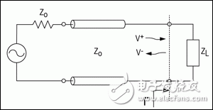
When an incident wave reaches a boundary, such as a load through a lossless transmission line (Figure 1), part of the energy is transmitted to the load, while part of the energy is reflected back. The reflection coefficient represents the ratio of the incident wave to the reflected wave:
Γ = V-/V+ (Equation 1)
Where V- is the reflected wave and V+ is the incident wave. The relationship between VSWR and voltage reflection coefficient (Γ) is:
VSWR = (1 + |Γ|)/(1 – |Γ|)(式2)

Figure 1. Transmission line circuit illustrating the impedance mismatch between the transmission line and the load.
The reflection at the boundary is Γ, with the incident wave being V+ and the reflected wave being V-.
VSWR can be measured directly using an SWR meter. RF test instruments such as vector network analyzers (VNA) can be used to measure the reflection coefficients of the input port (S11) and the output port (S22). S11 and S22 are equivalent to the reflection coefficients Γ of the input and output ports. VNAs mathematical models can also be used to directly calculate and characterize VSWR.
The return loss of the input and output ports can be calculated using the reflection coefficient S11 or S22:
RLIN = 20log10|S11| dB (Equation 3)
RLOUT = 20log10|S22| dB (Equation 4)
The reflection coefficient can be calculated from the characteristic impedance of the transmission line and the load impedance using the following formula:
Γ = (ZL - ZO)/(ZL + ZO)(式5)
Where ZL is the load impedance and ZO is the characteristic impedance of the transmission line (Figure 1).
VSWR can also be expressed in terms of ZL and ZO. Substituting equation 5 into equation 2, we get:
VSWR = [1 + |(ZL - ZO)/(ZL + ZO)|]/[1 - |(ZL - ZO)/(ZL + ZO)|] = \(ZL + ZO + |ZL - ZO|)/ (ZL + ZO - |ZL - ZO|)
如果ZL > ZO, |ZL - ZO| = ZL − ZO
but:
VSWR = (ZL + ZO + ZL - ZO)/(ZL + ZO - ZL + ZO) = ZL/ZO.(式6)
如果ZL < ZO, |ZL - ZO| = ZO - ZL
but:
VSWR = (ZL + ZO + ZO - ZL)/(ZL + ZO - ZO + ZL) = ZO/ZL.(式7)
We note that the VSWR mentioned above is a ratio relative to 1, for example, the VSWR is 1.5:1. There are two special cases of VSWR, ∞:1 and 1:1. When the load is open, the VSWR is ∞:1, and when the load is completely matched with the characteristic impedance of the transmission line, the VSWR is 1:1.
The definition of VSWR comes from the standing wave generated by the transmission line itself:
VSWR = |VMAX|/|VMIN|(8/)
Among them, VMAX is the maximum value of the standing wave voltage on the transmission line, and VMIN is the minimum value of the standing wave voltage on the transmission line. The maximum value is generated by the superposition of the incident wave and the reflected wave in the same direction. Therefore:
VMAX = V+ + V- (Equation 9)
The minimum is generated by the reverse superposition of the incident and reflected waves:
VMIN = V+ - V-(式10)
Substituting equation 9 and equation 10 into equation 8, we can get:
VSWR = |VMAX|/|VMIN| = (V+ + V-)/(V+ - V-)(式11)
Substituting equation 1 into equation 11, we get:
VSWR = V+(1 + |Γ|)/(V+(1 - |Γ|) = (1 + |Γ|)/(1 – |Γ|)(式12)
Formula 12 is equal to Formula 2 in this paper.
VSWR detection system
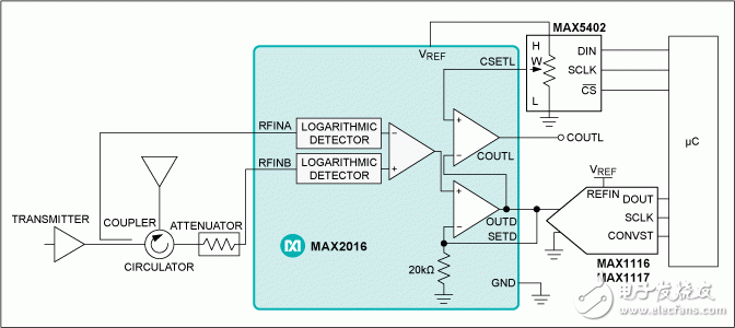
The MAX2016 is a dual-channel logarithmic detector/controller that is used with a circulator and attenuator to monitor the VSWR/return loss of an antenna. The MAX2016 outputs the difference between the two power detectors.
The MAX2016, together with the MAX5402 digital potentiometer and the MAX1116/MAX1117 ADC, forms a complete VSWR monitoring system (Figure 2). The digital potentiometer is used as a voltage divider for the MAX2016 output reference voltage. The internal voltage reference provides a typical current of 2mA, which is used to set the threshold voltage (CSETL) of the internal comparator. When the output voltage is above or below the threshold voltage (COUTL), an alarm output is generated. The operating voltage of the MAX1116 ADC is 2.7V to 3.6V, and the operating voltage of the MAX1117 ADC is 4.5V to 5.5V. The ADC can also use the MAX2216 to provide a voltage reference. The ADC and the microcontroller jointly monitor the VSWR of the antenna.

Figure 2. The companion ADC is used to build a real-time VSWR monitoring system,
and an external digital potentiometer is used to configure the comparator output (COUTL) alarm threshold.
Summarize
This tutorial explains that SWR or VSWR is a way to measure the imperfections and efficiency of a transmission line. VSWR is related to the reflection coefficient. A higher ratio indicates a greater mismatch, while 1:1 is a perfect match. Match or mismatch is determined by the maximum and minimum amplitude of the standing wave. SWR is the ratio of transmitted energy to reflected energy. The MAX2016 is used as an example to illustrate how to create a system to monitor the VSWR of an antenna.
Previous article:A brief discussion on the security design of smart grid
Next article:For digital engineers using FPGAs: How to simplify FPGA power supply
- Popular Resources
- Popular amplifiers
- High signal-to-noise ratio MEMS microphone drives artificial intelligence interaction
- Advantages of using a differential-to-single-ended RF amplifier in a transmit signal chain design
- ON Semiconductor CEO Appears at Munich Electronica Show and Launches Treo Platform
- ON Semiconductor Launches Industry-Leading Analog and Mixed-Signal Platform
- Analog Devices ADAQ7767-1 μModule DAQ Solution for Rapid Development of Precision Data Acquisition Systems Now Available at Mouser
- Domestic high-precision, high-speed ADC chips are on the rise
- Microcontrollers that combine Hi-Fi, intelligence and USB multi-channel features – ushering in a new era of digital audio
- Using capacitive PGA, Naxin Micro launches high-precision multi-channel 24/16-bit Δ-Σ ADC
- Fully Differential Amplifier Provides High Voltage, Low Noise Signals for Precision Data Acquisition Signal Chain
- LED chemical incompatibility test to see which chemicals LEDs can be used with
- Application of ARM9 hardware coprocessor on WinCE embedded motherboard
- What are the key points for selecting rotor flowmeter?
- LM317 high power charger circuit
- A brief analysis of Embest's application and development of embedded medical devices
- Single-phase RC protection circuit
- stm32 PVD programmable voltage monitor
- Introduction and measurement of edge trigger and level trigger of 51 single chip microcomputer
- Improved design of Linux system software shell protection technology
- What to do if the ABB robot protection device stops
- Analysis of the application of several common contact parts in high-voltage connectors of new energy vehicles
- Wiring harness durability test and contact voltage drop test method
- From probes to power supplies, Tektronix is leading the way in comprehensive innovation in power electronics testing
- From probes to power supplies, Tektronix is leading the way in comprehensive innovation in power electronics testing
- Sn-doped CuO nanostructure-based ethanol gas sensor for real-time drunk driving detection in vehicles
- Design considerations for automotive battery wiring harness
- Do you know all the various motors commonly used in automotive electronics?
- What are the functions of the Internet of Vehicles? What are the uses and benefits of the Internet of Vehicles?
- Power Inverter - A critical safety system for electric vehicles
- Analysis of the information security mechanism of AUTOSAR, the automotive embedded software framework
- TMS320F28335 Experimenter Board Kit
- OPA2369 Issues
- [Summary] Let's get our hands dirty and do a "labor" transformation of old things
- [GD32L233C-START Review] 9. IAP program upgrade - based on YMODEM protocol
- What is it like to ask programmers to write code by hand with pen and paper after a power outage?
- [Sipeed LicheeRV 86 Panel Review] III. Building a cross-compilation environment: success and failure
- I need help from a master, diesel engine electronic throttle pedal signal synchronization failure
- In three minutes, let me show you what load is.
- Data Structures in Embedded System Software Design (Full Version)
- When BLE meets MEMS——Introduction to HID Report Descriptor

 MAX4174AMEUK+T


 京公网安备 11010802033920号