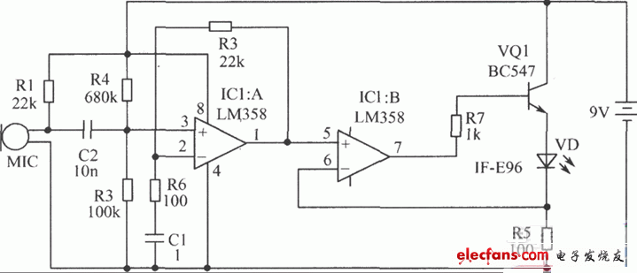
This circuit can transmit speech through 1mm plastic optical cable. The transmitter circuit board (KIT26 T) has a microphone and a circuit to modulate the LED light. The LED is installed in a plastic shell to facilitate the connection to the FO optical cable for transmission. On the receiver (KIT26 R) board there are photoelectric receivers, speakers and circuits for converting the detected light signals into electrical signals, amplifying and converting them into sound waves. The speech signal is transmitted in the optical cable in the form of light waves and is not affected by any electric and magnetic fields. The transmission distance is long and the anti-interference ability is strong. Each circuit board requires a 9V battery, but it is recommended to use a rectifier power supply for continuous use. 4.3m of 1mm diameter plastic optical cable is installed in the device. This line can well transmit signals through 183m optical cable. Note: The plastic optical cable used here is not 1μm glass optical cable. Glass optical cable can communicate over a longer distance (about 32km). Plastic optical cable is very convenient for experimental application and has obvious anti-interference effect for short-distance communication in an electronic noise environment. This circuit is assembled on a single-sided printed circuit board.
Working principle: The audio signal is initially a sound wave, which is converted into an electrical signal by the electronic microphone of the transmitter. This signal is amplified by the audio amplifier composed of LM358, and with the help of a separate transistor to control the terminal voltage of the LED, the electrical signal is converted into a light signal. The light signal is sent to the plastic optical cable. At the other end of the optical cable, the light signal shines on the photoelectric tube of the receiver. The photoelectric tube converts it into an electrical signal. This signal is amplified and sent to the speaker to be converted into sound waves.
Transmitter component selection: IC1 uses LM358 integrated circuit. VQ1 uses BC547 transistor. C1 uses 0.1μF single capacitor. VD uses IF-E96 photoelectric transmitter (pink dots on blue background). Other components are shown in the figure.
Receiver component selection: VT uses IF-D93 photodetector (black background with red dots). C2, C3, CA, and C6 all use 0.1μF single capacitors. Other components are shown in the figure.
Transmitter PCB:

Photoelectric receiver:

Previous article:Noise Filter Ferrite Beads
Next article:LM389 two-way wireless intercom circuit
- Popular Resources
- Popular amplifiers
- High signal-to-noise ratio MEMS microphone drives artificial intelligence interaction
- Advantages of using a differential-to-single-ended RF amplifier in a transmit signal chain design
- ON Semiconductor CEO Appears at Munich Electronica Show and Launches Treo Platform
- ON Semiconductor Launches Industry-Leading Analog and Mixed-Signal Platform
- Analog Devices ADAQ7767-1 μModule DAQ Solution for Rapid Development of Precision Data Acquisition Systems Now Available at Mouser
- Domestic high-precision, high-speed ADC chips are on the rise
- Microcontrollers that combine Hi-Fi, intelligence and USB multi-channel features – ushering in a new era of digital audio
- Using capacitive PGA, Naxin Micro launches high-precision multi-channel 24/16-bit Δ-Σ ADC
- Fully Differential Amplifier Provides High Voltage, Low Noise Signals for Precision Data Acquisition Signal Chain
- LED chemical incompatibility test to see which chemicals LEDs can be used with
- Application of ARM9 hardware coprocessor on WinCE embedded motherboard
- What are the key points for selecting rotor flowmeter?
- LM317 high power charger circuit
- A brief analysis of Embest's application and development of embedded medical devices
- Single-phase RC protection circuit
- stm32 PVD programmable voltage monitor
- Introduction and measurement of edge trigger and level trigger of 51 single chip microcomputer
- Improved design of Linux system software shell protection technology
- What to do if the ABB robot protection device stops
- Analysis of the application of several common contact parts in high-voltage connectors of new energy vehicles
- Wiring harness durability test and contact voltage drop test method
- From probes to power supplies, Tektronix is leading the way in comprehensive innovation in power electronics testing
- From probes to power supplies, Tektronix is leading the way in comprehensive innovation in power electronics testing
- Sn-doped CuO nanostructure-based ethanol gas sensor for real-time drunk driving detection in vehicles
- Design considerations for automotive battery wiring harness
- Do you know all the various motors commonly used in automotive electronics?
- What are the functions of the Internet of Vehicles? What are the uses and benefits of the Internet of Vehicles?
- Power Inverter - A critical safety system for electric vehicles
- Analysis of the information security mechanism of AUTOSAR, the automotive embedded software framework
- Review summary: Free review: The cheapest Hongmeng development board Neptune is here
- Has anyone used the software every circuit?
- Excuse me, is there any tutorial for assembling MCS-51 microcontroller?
- [Hardcore Science] What is a bipolar four-quadrant power supply? Is the power amplifier also a bipolar four-quadrant power supply?
- Nonvolatile MRAM and its cell structure
- FPGA controls DSP power-on reset procedure
- Sampling period
- Ask for help, recommendation, keywords
- It's holiday time, but we're still working overtime every day
- Tuya Sandwich Wi-Fi & BLE SoC NANO Main Control Board WBRU+ Unboxing

 TC52N2741ECTRT


 京公网安备 11010802033920号