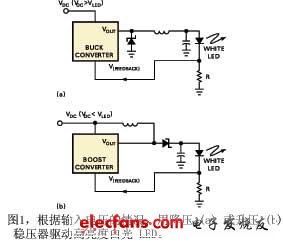
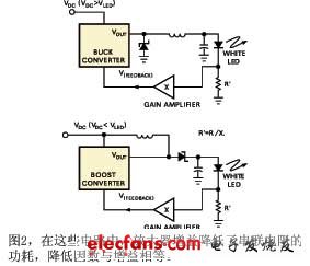
Lighting using LEDs has become more popular due to the availability of high-power, high-efficiency white (and other color) LEDs. Since LEDs are current-controlled devices, the typical control circuit is to adjust the current through the LED to maintain consistent brightness. To make the best use of the power, users often use switching converter circuits for LEDs, which can be either buck or boost converters, depending on the input DC voltage. Figure 1 shows the structure of a typical buck and boost converter white LED driver circuit. White LEDs add a series resistor, R, which determines the current through the LED. The value of the resistor depends on the required LED current and the feedback voltage required by the buck/boost converter. For example, an average current of 100mA through the LED and a feedback voltage of 1.23V requires a resistor value of 12Ω. To reduce the power dissipated in the series resistor, engineers typically use the circuit structure shown in Figure 2. In this circuit, the gain of the amplifier reduces the power dissipated in the series resistor by a factor equal to the gain.

The circuit configurations in Figures 1 and 2 work well for regulating the current through the LED, provided that the ambient temperature remains constant. However, the brightness of white and other color LEDs is a function of temperature and varies greatly with temperature (References 2 and 3). Over a temperature range of 100°C, the brightness varies from 40% to 150%. Therefore, if changes in ambient temperature are expected, it is not sufficient to regulate only the current through the LED.
Not an efficient way to control an LED. An alternative is to use optical feedback to control the LED.
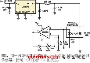
However, instead of using an expensive light sensor and amplifier circuit, you can use a suitable LED as a light sensor (Reference 4). Figure 3 shows a white-light LED controller using an inexpensive buck regulator IC (the adjustable LM2575). A 3-mm red LED in a clear package is used to detect the light from the 10-mm white LED. The spectrum of the white LED is broad enough to excite the red LED used as a sensor. For a 60-mA test current through the white LED, the voltage across the red LED sensor is about 40 mV. Because the circuit uses the voltage from the red LED sensor as feedback for the buck regulator, an amplifier with a gain of about 30 must be used because the internal reference voltage of the LM2575 buck regulator is 1.23 V. Resistors R1, R2, and R3 control the gain of the amplifier, which consists of an inexpensive LM358 dual op amp. The input DC voltage powers the op amp. Resistors R1, R2, and R3 have values of 270 Ω, 560 Ω, and 10 kΩ, respectively. Since R2 is a variable resistor, changing its setting value changes the gain, and thus changes the current through the white LED. Therefore, R2 is used as a brightness control. The amplifier gain ranges from 28 to 84, depending on the setting of R2.

The red LED acts as a sensor and is mounted to the side of the white LED, so only a portion of the white LED's radiated light is used. The top of the 3mm red LED is processed into a flat surface, and then the 3mm red LED is fixed to the side of the white LED with a drop of super glue.

The LM2575 buck regulator adjusts the output voltage by changing its duty cycle. If the output light intensity of the white LED decreases due to temperature rise, the voltage of the red LED sensor also decreases proportionally. The output of the red LED sensor is connected to the feedback input terminal (pin 4) of the regulator IC, and the regulator IC accordingly increases the output voltage duty cycle of the white LED, thereby stabilizing the brightness. When the ambient temperature drops, the light intensity of the white LED increases, and the regulator reduces the output voltage, which also achieves the purpose of stabilizing the brightness of the white LED.
Previous article:Using the TL431 Shunt Regulator to Limit High AC Input Voltage
Next article:Design of Embedded Controller Based on CORBA Technology
- Popular Resources
- Popular amplifiers
- High signal-to-noise ratio MEMS microphone drives artificial intelligence interaction
- Advantages of using a differential-to-single-ended RF amplifier in a transmit signal chain design
- ON Semiconductor CEO Appears at Munich Electronica Show and Launches Treo Platform
- ON Semiconductor Launches Industry-Leading Analog and Mixed-Signal Platform
- Analog Devices ADAQ7767-1 μModule DAQ Solution for Rapid Development of Precision Data Acquisition Systems Now Available at Mouser
- Domestic high-precision, high-speed ADC chips are on the rise
- Microcontrollers that combine Hi-Fi, intelligence and USB multi-channel features – ushering in a new era of digital audio
- Using capacitive PGA, Naxin Micro launches high-precision multi-channel 24/16-bit Δ-Σ ADC
- Fully Differential Amplifier Provides High Voltage, Low Noise Signals for Precision Data Acquisition Signal Chain
- LED chemical incompatibility test to see which chemicals LEDs can be used with
- Application of ARM9 hardware coprocessor on WinCE embedded motherboard
- What are the key points for selecting rotor flowmeter?
- LM317 high power charger circuit
- A brief analysis of Embest's application and development of embedded medical devices
- Single-phase RC protection circuit
- stm32 PVD programmable voltage monitor
- Introduction and measurement of edge trigger and level trigger of 51 single chip microcomputer
- Improved design of Linux system software shell protection technology
- What to do if the ABB robot protection device stops
- Huawei's Strategic Department Director Gai Gang: The cumulative installed base of open source Euler operating system exceeds 10 million sets
- Download from the Internet--ARM Getting Started Notes
- Learn ARM development(22)
- Learn ARM development(21)
- Learn ARM development(20)
- Learn ARM development(19)
- Learn ARM development(14)
- Learn ARM development(15)
- Analysis of the application of several common contact parts in high-voltage connectors of new energy vehicles
- Wiring harness durability test and contact voltage drop test method
- [Silicon Labs BG22-EK4108A Bluetooth Development Review] 1. Unboxing
- Why is the output ripple of the circuit I designed so large?
- COCOFLY Tutorial - Crazy Shell Drone Series Quick Start [3] OPENMV Script Burning
- [Telink's new generation of low-power, high-performance, multi-protocol wireless kit B91 review] HomeAssistant+B91zigbee network access
- LOTO Lesson 1: RC Resistor-Capacitor Practice --- Low-Pass Filter PWM to DC
- [Summary] DCExpert takes you to the "full stack" hands-on: rechargeable touch-controlled creative LED lamp based on ESP8266
- UWB (Ultra-Wideband)
- 【Perf-V Evaluation】+Test of serial communication function
- After a busy year, I finally have a holiday.
- How to ensure high accuracy of measurement results due to nonlinear changes in NTC resistors

 LT6700CDCB-2#PBF


 京公网安备 11010802033920号