1 Introduction
Voltage operational amplifiers are basic active devices in analog circuit design. The operating frequency of a circuit composed of ordinary voltage operational amplifiers is relatively low. Current feedback amplifiers (CFA) are a new type of operational amplifier. They not only provide a bandwidth close to a constant value, but also have a high conversion rate. The circuit composed of them has better performance than the circuit composed of OTA in terms of frequency characteristics and dynamic range [1-30]. In recent years, current feedback amplifiers have been applied in second-order filter circuits [6-10], and literature on voltage-mode or current-mode biquadratic filters composed of current feedback amplifiers (CFA) has been continuously reported. There are two main forms: one is a single-input multi-output filter; the other is a three-input single-output filter. However, according to the literature, most circuits use a large number of CFA devices. This paper proposes a three-input single-output voltage-mode universal second-order filter circuit. The circuit is composed of only two current feedback amplifiers (CFAs), two capacitors, and three resistors. The circuit structure is simple and can realize second-order low-pass, band-pass, high-pass, notch, and full-pass filter functions. The circuit was simulated using PSpice. The simulation results showed that the circuit design was correct and the theoretical analysis was consistent with the simulation results.
2 CFA circuit structure and principle
The current feedback amplifier (CFA) is a four-port device as shown in Figure 1. Its circuit transfer characteristics are:
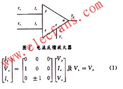
That is, Iy=0, Vx=Vy, Ix=±Iz, Vo=Vz. In formula (1), "+" corresponds to CFA+, and "-" corresponds to CFA-. It can be seen that the voltage at the x-terminal follows the voltage at the y-terminal, and the current at the z-terminal follows the current at the x-terminal. The y-terminal is a high-impedance input, Iy=0, and the voltage at the z-terminal follows the voltage at the o-terminal [6-9].
3 Second-order filter principle
This article uses the filter circuit shown in Figure 2, which is composed of 2 CFAs, 2 capacitors and 3 resistors. Circuit analysis of the circuit in Figure 2 yields:

From the above equation, the circuit current transfer function can be obtained:

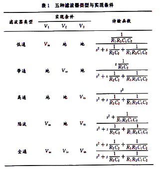
From formula (6), we can know that by changing the input signals V1, V2, and V3, low-pass, band-pass, high-pass, notch, and all-pass filter functions can be realized respectively. The corresponding relationship between the realization conditions and the filter types is shown in Table 1.
The circuit pole parameters are:

From equations (7) and (9), it can be seen that the pole angular frequency and the pole quality factor can be adjusted independently.
According to the definition of sensitivity,
![]() the change sensitivity of the characteristic frequency ωP,QP relative to the resistance element and the capacitance element, ωp,QP, the passive sensitivity is:
the change sensitivity of the characteristic frequency ωP,QP relative to the resistance element and the capacitance element, ωp,QP, the passive sensitivity is:
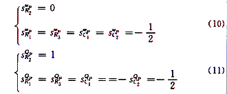
From equations (10) and (11), we can see that the passive sensitivity of ωp,QP is relatively small.
Considering the non-ideal characteristics of CFA, its port characteristics are:

Among them: a=1-ε1, ︱ε1︱<<《1, ε1 represents the current tracking error of the current feedback amplifier, β=1-ε2, ︱ε2︱<<1, ε2 represents the input voltage tracking error of the current feedback amplifier, γ1=1-ε3, ︱ε3 ︱<<1, ε3 represents the output voltage tracking error of the current feedback amplifier. Through analysis, the output voltage can be obtained as:
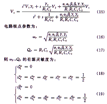
From equations (18) and (19), it can be seen that the active sensitivity of ωP and QP is also small.
4 Circuit Simulation
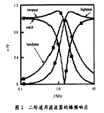
In order to verify the correctness of the designed filter circuit, the author used PSpice to simulate the circuit. When R1=R2=R3=1 kΩ, C1=C2=0.1 μF, from equation (8), we get: fp=1.59 kHz. Under PSpice9.1, the circuit shown in Figure 2 was simulated, and the amplitude-frequency characteristics (as shown in Figure 3) were consistent with the required technical parameters.
5 Conclusion
This paper proposes a voltage mode universal second-order filter circuit consisting of only two current feedback amplifiers (CFAs), two capacitors and three resistors, which can realize second-order low-pass, band-pass, high-pass, band-stop and all-pass filter functions. The circuit analysis was carried out to obtain the voltage transfer function and circuit parameters. The filter circuit was simulated using PSpice. The simulation results show that the filter circuit design is correct and the theoretical analysis is consistent with the simulation results. The circuit has the following characteristics:
(1) Able to realize voltage mode second-order low-pass, band-pass, high-pass, notch, and all-pass filtering functions;
(2) The circuit structure is simple;
(3) It has fewer components;
(4) Passive and active sensitivity is low;
(5)ωP, QP are adjustable
(6) The circuit is easy to implement.
Previous article:A Solution for Estimating the Temperature Rise of Hot-Swap MOSFETs
Next article:The Harm of △I Noise in Digital Circuits
- High signal-to-noise ratio MEMS microphone drives artificial intelligence interaction
- Advantages of using a differential-to-single-ended RF amplifier in a transmit signal chain design
- ON Semiconductor CEO Appears at Munich Electronica Show and Launches Treo Platform
- ON Semiconductor Launches Industry-Leading Analog and Mixed-Signal Platform
- Analog Devices ADAQ7767-1 μModule DAQ Solution for Rapid Development of Precision Data Acquisition Systems Now Available at Mouser
- Domestic high-precision, high-speed ADC chips are on the rise
- Microcontrollers that combine Hi-Fi, intelligence and USB multi-channel features – ushering in a new era of digital audio
- Using capacitive PGA, Naxin Micro launches high-precision multi-channel 24/16-bit Δ-Σ ADC
- Fully Differential Amplifier Provides High Voltage, Low Noise Signals for Precision Data Acquisition Signal Chain
- Innolux's intelligent steer-by-wire solution makes cars smarter and safer
- 8051 MCU - Parity Check
- How to efficiently balance the sensitivity of tactile sensing interfaces
- What should I do if the servo motor shakes? What causes the servo motor to shake quickly?
- 【Brushless Motor】Analysis of three-phase BLDC motor and sharing of two popular development boards
- Midea Industrial Technology's subsidiaries Clou Electronics and Hekang New Energy jointly appeared at the Munich Battery Energy Storage Exhibition and Solar Energy Exhibition
- Guoxin Sichen | Application of ferroelectric memory PB85RS2MC in power battery management, with a capacity of 2M
- Analysis of common faults of frequency converter
- In a head-on competition with Qualcomm, what kind of cockpit products has Intel come up with?
- Dalian Rongke's all-vanadium liquid flow battery energy storage equipment industrialization project has entered the sprint stage before production
- Allegro MicroSystems Introduces Advanced Magnetic and Inductive Position Sensing Solutions at Electronica 2024
- Car key in the left hand, liveness detection radar in the right hand, UWB is imperative for cars!
- After a decade of rapid development, domestic CIS has entered the market
- Aegis Dagger Battery + Thor EM-i Super Hybrid, Geely New Energy has thrown out two "king bombs"
- A brief discussion on functional safety - fault, error, and failure
- In the smart car 2.0 cycle, these core industry chains are facing major opportunities!
- The United States and Japan are developing new batteries. CATL faces challenges? How should China's new energy battery industry respond?
- Murata launches high-precision 6-axis inertial sensor for automobiles
- Ford patents pre-charge alarm to help save costs and respond to emergencies
- New real-time microcontroller system from Texas Instruments enables smarter processing in automotive and industrial applications
- Talk about the understanding of private network communication
- How to Make DSP Digital Oscillator Generate Phase-Shifted Sine Wave
- About the problem of modifying the frequency offset of CC2650 chip
- Zigbee packet capture analysis - Introduction
- About STM32 sampling pressure sensor value
- Open source Linux phone designed with KiCad
- MSP430F5529 MCP4725 Program
- [STM32WB55 Review] This Nucleo is a little special
- HIFU ultrasonic knife (high energy focusing control circuit)
- ARM transplantation encounters a long wait for a solution

 CVPR 2023 Paper Summary: Adversarial Attack and Defense
 Research on lithium battery SOC estimation method combining circuit equivalence and UKF-EKF


 京公网安备 11010802033920号