Communication cable is one of the main media for information exchange. In the construction and maintenance of communication and computer network projects, the disconnection, short circuit, mixed line and other faults of transmission cable lines often trouble network construction and maintenance personnel. This article will introduce a cable tester, which can not only determine the nature and location of disconnection, short circuit and mixed line faults in cable lines, but also test the frequency characteristics of cables, complete automatic cable alignment, and solve some problems often encountered in the construction and maintenance of information systems.
1 Functions of cable tester
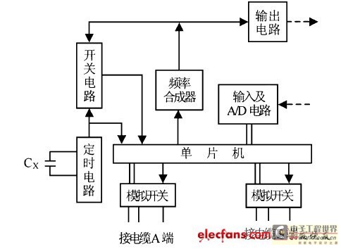
According to the problems that often need to be solved in the construction and daily maintenance of information systems, the following functions are designed for this tester: 1) It can test the frequency characteristics of network cables to determine the bandwidth (transmission rate) of the transmission system. 2) It can realize automatic alignment of network cables, which can greatly improve the efficiency and accuracy in the construction and maintenance of most cables. 3) It can determine the nature of the line break fault and determine the line breakpoint. 4) It can determine the short circuit and mixed line faults between lines and determine the fault point. The composition of the tester is shown in Figure 1.

Figure 1 Cable tester block diagram
2 Testing Principle of Cable Tester
2.1 Frequency characteristics
The frequency characteristics of a cable refer to the characteristics of the cable's attenuation of the transmitted signal as the signal frequency changes. Due to the distributed capacitance and inductance between the cable cores, the attenuation of the sinusoidal signal changes as the frequency of the transmitted signal changes. If a signal of different frequencies with a stable amplitude is injected into the A end of the cable, and the signal amplitude corresponding to the frequency of the A end after transmission through the cable is tested at the B end, the frequency characteristics of the cable can be obtained.
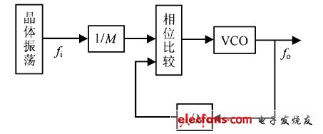
According to the working principle of the frequency synthesizer (as shown in Figure 2), the relationship between the output frequency fo and the reference frequency fi is:
Where M and N are the division ratios of the divider.

Figure 2 Frequency synthesizer block diagram
It can be seen from formula (1) that by changing the values of M and N, the frequency synthesizer in Figure 1 can output frequency signals with the same stability as the reference frequency at different intervals. The fo signal is amplified and stabilized by the output circuit, and injected into the A end of the cable by the impedance matching interface circuit; at the B end of the cable, the signal after cable transmission is connected to the input circuit for amplification, and converted into a digital signal by the APD (analog-to-digital) converter and sent to the microcontroller for detection and processing. On the one hand, the microcontroller controls the size of M and N to achieve the purpose of outputting different frequencies, and on the other hand, it outputs a handshake synchronization signal to the other party. 2.2 Automatic alignment
If a DC signal is injected into the A end of the line, and there is only one wire at the B end that can detect the signal, then the A and B ends are connected to the same wire; if there are more than two access wires at the B end that can detect the signal, there must be a mixed line somewhere in the cable. If no access wire at the B end can detect the signal, then there must be a breakpoint somewhere in the line.
As shown in Figure 1, the analog switch controlled by the single-chip microcomputer and the dedicated circuit connects the DC test signal to different test lines at the A end, and the analog switch access point at the B end is controlled by the single-chip microcomputer to detect the signal. The A and B ends are synchronously controlled by the master-slave signal (a pair of signal lines needs to be found in the cable as the handshake contact line), and the corresponding conditions of each line pair, such as on, short, off, and mixed lines, are judged and recorded.
2.3 Wire break location
Due to the consistency of the cable manufacturing structure, the size of the distributed capacitance per unit length of the cable is the same. Therefore, by testing the distributed capacitance between each pair of cable wires, the length of the cable line or the breakpoint of the cable pair can be measured.
According to the working principle of the monostable trigger timing circuit, the relationship between the timing time t and the timing elements R, C is:
Where t is the timing time, R is the resistance value of the timing resistor, C is the capacitance value of the timing capacitor, and k is a constant related to the circuit, generally 3~5.
Since the timing time is linearly related to the external capacitance, if the pulse signal of frequency f is counted within a timing cycle, the relationship between the number of pulses n and t is:
Substituting formula (2) into formula (3), we get:
Therefore, the measured capacitance can be used as the timing element of the circuit to sample and count a stable reference frequency f signal within a timing cycle. The larger the measured capacitance, the longer the sampling time and the more pulses are counted. The number of pulses can linearly reflect the measured capacitance value.
If the capacitance per unit length of a cable is known to be Cx (marked on the cable inspection certificate before leaving the factory), and the measured capacitance is Cp, then the cable length is:
Substituting formula (4) into formula (5), we get:
As shown in Figure 1, the timing circuit can be composed of a circuit with a 555 integrated circuit as the core, the switch circuit can be composed of a gate circuit, and the counting frequency signal is the output signal of the frequency synthesizer. The value of M and N can be changed by the single-chip microcomputer to achieve the purpose of changing the test range. While controlling the switch circuit, the timing signal is sent to the single-chip microcomputer as the interrupt signal source of the single-chip microcomputer counting interrupt.
2.4 Mixed Line Positioning
When the lines are mixed, the loop DC resistance between the lines can be measured for testing. Based on the resistance value of the cable core wire per kilometer, the measured resistance value can be converted into the distance between the mixed point and the test point.
However, when the cable core wires are mixed somewhere in the middle of the cable, the contact resistance is uncertain due to the different degrees of mixing, and it is an unknown number. Therefore, it is necessary to try to eliminate the influence of contact resistance. The influence of contact resistance can be eliminated by using the two-measurement method.

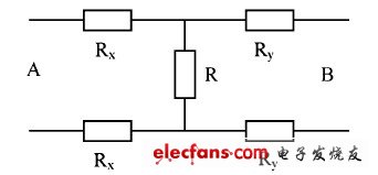
Figure 3 Schematic diagram of mixed line positioning test
As shown in Figure 3, let the mixed line contact resistance be R, the line resistance of a single wire between the mixed line point and the test point A end be Rx, and the measured mixed line loop resistance be Ra; the line resistance of a single wire between the mixed line point and the test point B end is Ry, and the measured mixed line loop resistance is Rb; then:

From the above formula, we can get:

Rx + Ry is the resistance of a single conductor in the entire length of the cable, so Rx or Ry can be calculated using the above formula. Based on the resistance value per kilometer of the cable, the mixed line point can be determined by Rx or Ry.
3. Cable tester control program flow
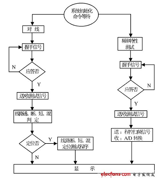
The system is first initialized, and then tested according to the test process based on different test requirements, and the test results are displayed on the monitor.
The test process of each part is shown in Figure 4.

Figure 4 Test system control program flow chart
4 Conclusion
The cable tester based on single chip control introduced in this paper can be integrated into a portable field tester. Through theoretical analysis and experimental verification, the tester can achieve accurate testing and is widely used in communication network engineering construction and maintenance.
Previous article:Design of temperature measurement system based on single chip microcomputer and PC serial port communication
Next article:A design scheme for an intelligent car robot
- High signal-to-noise ratio MEMS microphone drives artificial intelligence interaction
- Advantages of using a differential-to-single-ended RF amplifier in a transmit signal chain design
- ON Semiconductor CEO Appears at Munich Electronica Show and Launches Treo Platform
- ON Semiconductor Launches Industry-Leading Analog and Mixed-Signal Platform
- Analog Devices ADAQ7767-1 μModule DAQ Solution for Rapid Development of Precision Data Acquisition Systems Now Available at Mouser
- Domestic high-precision, high-speed ADC chips are on the rise
- Microcontrollers that combine Hi-Fi, intelligence and USB multi-channel features – ushering in a new era of digital audio
- Using capacitive PGA, Naxin Micro launches high-precision multi-channel 24/16-bit Δ-Σ ADC
- Fully Differential Amplifier Provides High Voltage, Low Noise Signals for Precision Data Acquisition Signal Chain
- Innolux's intelligent steer-by-wire solution makes cars smarter and safer
- 8051 MCU - Parity Check
- How to efficiently balance the sensitivity of tactile sensing interfaces
- What should I do if the servo motor shakes? What causes the servo motor to shake quickly?
- 【Brushless Motor】Analysis of three-phase BLDC motor and sharing of two popular development boards
- Midea Industrial Technology's subsidiaries Clou Electronics and Hekang New Energy jointly appeared at the Munich Battery Energy Storage Exhibition and Solar Energy Exhibition
- Guoxin Sichen | Application of ferroelectric memory PB85RS2MC in power battery management, with a capacity of 2M
- Analysis of common faults of frequency converter
- In a head-on competition with Qualcomm, what kind of cockpit products has Intel come up with?
- Dalian Rongke's all-vanadium liquid flow battery energy storage equipment industrialization project has entered the sprint stage before production
- Allegro MicroSystems Introduces Advanced Magnetic and Inductive Position Sensing Solutions at Electronica 2024
- Car key in the left hand, liveness detection radar in the right hand, UWB is imperative for cars!
- After a decade of rapid development, domestic CIS has entered the market
- Aegis Dagger Battery + Thor EM-i Super Hybrid, Geely New Energy has thrown out two "king bombs"
- A brief discussion on functional safety - fault, error, and failure
- In the smart car 2.0 cycle, these core industry chains are facing major opportunities!
- Rambus Launches Industry's First HBM 4 Controller IP: What Are the Technical Details Behind It?
- The United States and Japan are developing new batteries. CATL faces challenges? How should China's new energy battery industry respond?
- Murata launches high-precision 6-axis inertial sensor for automobiles
- Ford patents pre-charge alarm to help save costs and respond to emergencies
- Three elements of switching power supplies and digital devices
- Muddy tax control
- [Ateli Development Board AT32F421 Review] 7. Kuga registers jointly light up OLED
- ARM Development Process
- EL817C Optocoupler Transmission Ratio Problem
- Keysight Technologies N9020A 3.6G spectrum analyzer special sale: 8500/unit
- STM32+photosensitive sensor+serial port receiving light intensity source program is successfully produced
- How does the uart.write function output three bytes of 0XFF 0XFF 0XFF (HEX data, not string data)?
- Electric vehicles use silicon carbide power devices to successfully move out of the laboratory
- Chinese programmers VS American programmers, so vivid...

 Design paper of dot matrix electronic display screen
 *** *** *** *** *** *** ***** ** Two wire/I2C Bus READ/WRITE Sample Routines of Microchip s ** 2
 CLC412A8B


 京公网安备 11010802033920号