This paper designs a lighting control system for smart home applications by combining remote control technology and single-chip microcomputer . The system is a control system based on single-chip microcomputer, which controls the system lighting by remote control. This solution mainly solves the transmission and reception of signals, processes different signals after receiving and processing the signals, and realizes the switching and brightness adjustment of the light bulbs through software programming.
introduction
Smart home refers to the use of advanced computer technology, network communication technology, and integrated wiring technology to organically combine various subsystems related to home life, and through coordinated management, make home life more comfortable, safe, and efficient.
With the improvement of people's living standards and the development of electronic technology, home intelligence has begun to enter our daily life. People are no longer satisfied with the button-type manual switch to control the lamps, and have developed a remote control system for professional lighting control with a higher level of intelligence, which is low in cost, high in quality, and flexible and convenient to use. Due to its small size, low power consumption, strong functions and low cost, infrared remote control has become the most widely used means of communication and remote control.
1 Basic principles of infrared remote control
Infrared remote control uses infrared rays (also known as infrared light) to transmit control signals to achieve long-distance control of the controlled object. Specifically, the transmitter sends out infrared command signals, which are received by the receiver and processed and identified, and then passed through the corresponding control chip, and finally the various functions of the controlled object are remotely controlled according to the different signals received.
The infrared transmitter consists of a command button, a signal generating circuit, a frequency modulation circuit, a driving circuit and an infrared transmitting device, as shown in Figure 1. When the command button is pressed, the command signal generating circuit generates the required control command signal.
The control command signals here are distinguished by certain different characteristics. The commonly used characteristics to distinguish command signals are frequency characteristics and code group characteristics, that is, different frequencies or different coded telecommunication codes are used to represent different commands. These different command signals are frequency modulated, and finally the infrared emitting device is driven by the driving circuit to send out infrared remote control command signals.

Figure 1 Composition of infrared emission
The infrared receiver consists of an infrared receiving device, a preamplifier circuit, a signal demodulation circuit, and a command detection circuit, as shown in Figure 2. When the infrared receiving device receives the infrared command signal from the transmitter, it converts the infrared light signal into an electrical signal and sends it to the preamplifier for amplification. After being demodulated by the demodulator, the command signal detection circuit detects the command signal to achieve various operations.

Figure 2 Composition of infrared receiver
To realize the remote control function of the system, it is necessary to first select the method of signal command transmission. According to the remote control method and the user occasion, these control signal characteristics can be encoded in various combinations. Such as the combination of voltage polarity, the combination of electrical signal phase, the combination of electrical signal amplitude, the combination of frequency, the combination of pulse width, phase, amplitude and other parameters and pulse coding combination. The pulse coding combination method has the advantages of large command capacity, strong anti-interference ability, good confidentiality and easy to implement with logic circuits, and has been widely used.
2 System Hardware Circuit Design
The infrared remote control circuit consists of a transmitting circuit and a receiving circuit. The transmitting part consists of a key switch circuit, a control chip, and an infrared transmitting circuit. When the remote control button is pressed, the microcontroller generates a corresponding control signal, which is transmitted through the infrared transmitting diode. The receiving part consists of an infrared receiving head, a control chip, and a dimming circuit. When the infrared receiver receives the control pulse, it is processed by the microcontroller to determine whether to dim or switch the light, and perform the corresponding operation as needed. The receiving system is powered by a single 5V power supply. As shown in the figure below:
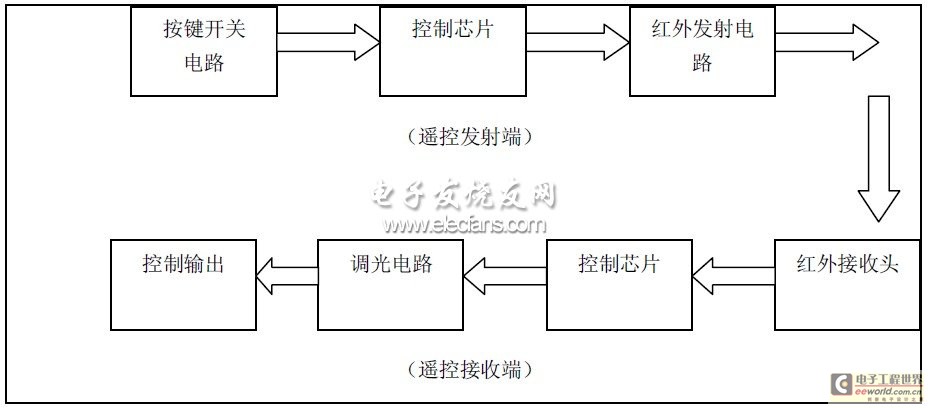
Figure 3 System design block diagram
2.1 Remote control system main control chip
The AT89C51 chip of the 51 series is selected in this system. The AT89C51 is a low-voltage, high-performance CMOS 8-bit microprocessor with 4k bytes of flash programmable and erasable read-only memory (FPEROM), commonly known as a single-chip computer. The device is manufactured using ATMEL's high-density non-volatile memory manufacturing technology and is compatible with the industry-standard MCS-51 instruction set and output pins. Because it combines a multifunctional 8-bit CPU and flash memory in a single chip, ATMEL's AT89C51 is an efficient microcontroller that provides a flexible and inexpensive solution for many embedded control systems. The AT89C51 is a low-power, high-performance single-chip computer with 40 pins, 32 external bidirectional input/output (I/O) ports, and contains 2 external interrupt ports, 2 16-bit programmable timer counters, and 2 full-duplex serial communication ports. The AT89C51 can be programmed in the conventional way or online.
It combines a general-purpose microprocessor and Flash memory together, especially the repeatedly erasable Flash memory, which can effectively reduce development costs.
In the design of this system, how the signal sent by the microcontroller is recognized by the infrared transmitting tube and whether the transmitting tube can transmit the infrared signal normally are the key issues that the transmitting circuit needs to solve.
To transmit infrared signals, an infrared emitting device is required. An infrared light emitting diode is a light emitting diode that can generate infrared light. The infrared light emitting diodes currently in widespread use emit infrared light with a wavelength of about 940nm. They have the same appearance as ordinary light emitting diodes, but with different colors. Common infrared emitting diodes are black and transparent. The biggest difference between them and ordinary light emitting diodes is that the light they emit is invisible light, while ordinary light emitting diodes emit visible light of various colors [5]. Generally, infrared light emitting diodes are divided into two structural forms: one is a remote control emitting infrared light emitting diode (i.e., the most commonly used infrared emitting diode used in handheld remote controls); the other is a short-range emitting infrared light emitting diode, which integrates the emission and reception of infrared light. Since this design implements home remote control, the first type can be used.
As shown in Figure 4, it is the system remote control transmission principle diagram. Port P1.0 is the key input port; port P2.0 is the infrared transmission port, which is used to output 38kHz carrier code. The pulse is amplified by 9013 (NPN) and then output by the infrared transmitting tube; pin 9 is the reset pin of the microcontroller, which uses an RC manual reset circuit; pins 18 and 19 are connected to the crystal oscillator.
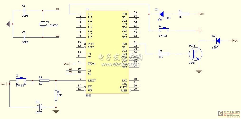
Figure 4 Infrared emission circuit diagram
2.3 Infrared receiving circuit module
1). Introduction to infrared receiving devices.
The general infrared receiver is mainly composed of integrated circuits plus resistors and capacitors, infrared receiving tubes and optical filters. The circuit design is relatively complicated and inconvenient in practical applications. The infrared remote control receiver SM0038 integrates infrared receiving tubes, preamplifiers and demodulators, has no external circuits, is small in size, has good sealing, high sensitivity, is easy to use, uses a low-power infrared transmitting tube to transmit signals, and has a receiving distance of up to 35 meters. It is also inexpensive. It has only three pins, namely the positive power supply, the negative power supply and the signal output terminal. Its operating voltage is about 5V, and the receiving frequency is 38kHz. Its main functions include amplification, frequency selection, and demodulation. The input signal must be a modulated signal. This minimizes the circuit, and the sensitivity and anti-interference performance are very good. It is an ideal device for receiving infrared signals. As shown in Figure 5:

Figure 5 SM0038
2). Design of receiving circuit and dimming circuit.
The implementation of the receiving circuit and dimming circuit are both realized through relays. A resistor is connected in series to each relay to form a loop. This circuit connects four relay loops in parallel and connects them to the P0 port. When all four relays are closed, the light is the brightest. When three relays are working, the light is brighter. When two relays are working, the light is the second brightest. When one relay is working, the light is the darkest. When none of the four relays are working, the light bulb is in the off state. The receiving circuit diagram is shown in Figure 6:
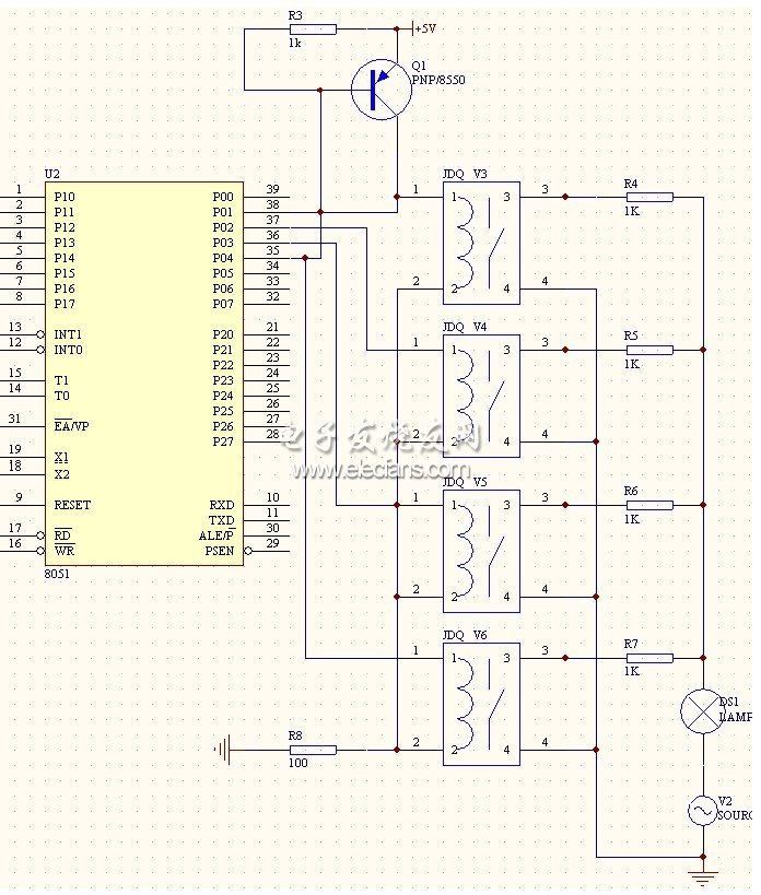
Figure 6 Receiving circuit diagram
3 System Software Design
The demodulation center frequency of the infrared receiver SM0038 used in this system is 38KHz, so the transmission frequency is also 38kHz. This circuit uses one key and one coding method to control the home lights. The receiving end adjusts the brightness of the lights according to the number of different codes received. Every time the P1.0 port is low, the confirmation key is pressed, and a code is transmitted from the P2.0 port. When the receiving end receives the code, it judges whether the first low level is greater than 2ms. If so, it judges whether it is the correct code. If so, num is increased by 1, and the brightness is dimmed by one level.
3.1. Remote control transmission program control flow chart
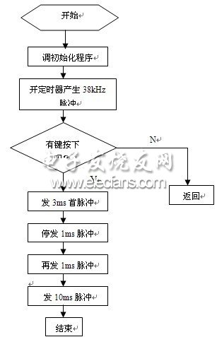
Figure 7 Launch procedure flow chart
After the initialization program, start the timer to generate 38kHz pulses, and then determine whether a key is pressed. When a key is pressed, a frame of pulses is sent according to the time set by the timer. First, a 3ms high level is sent, then a 1ms low level, a 1ms high level, and then a 10ms stop.
3.2. Remote control receiving program control flow chart
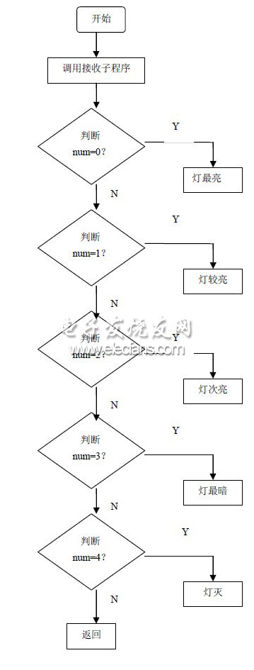
Figure 8 Flowchart of dimming procedure for receiving part
The receiving end uses the query mode to receive. When the query finds that the P1.0 port is at a low level, the accumulator works, and the brightness and switch of the control lamp are determined by the number of variables in the accumulator. When num is 0, the light is the brightest, and adding 1 dims it by one level. When num is equal to 4, all relays are disconnected and the light goes out.
4 Conclusion
In order to reduce the complexity of the circuit, I use a single-chip microcomputer to implement software encoding and decoding, which greatly improves the flexibility of the circuit and reduces the cost. Only one key can be used to turn a lamp on and off and adjust the brightness. If a push button switch is changed to a matrix keyboard, the switch and brightness control of lamps in the whole house can be achieved, which is very practical.
Previous article:TD-SCDMA Network Automatic Monitoring System Solution
Next article:The right way to speed up RF device testing
- Popular Resources
- Popular amplifiers
- High signal-to-noise ratio MEMS microphone drives artificial intelligence interaction
- Advantages of using a differential-to-single-ended RF amplifier in a transmit signal chain design
- ON Semiconductor CEO Appears at Munich Electronica Show and Launches Treo Platform
- ON Semiconductor Launches Industry-Leading Analog and Mixed-Signal Platform
- Analog Devices ADAQ7767-1 μModule DAQ Solution for Rapid Development of Precision Data Acquisition Systems Now Available at Mouser
- Domestic high-precision, high-speed ADC chips are on the rise
- Microcontrollers that combine Hi-Fi, intelligence and USB multi-channel features – ushering in a new era of digital audio
- Using capacitive PGA, Naxin Micro launches high-precision multi-channel 24/16-bit Δ-Σ ADC
- Fully Differential Amplifier Provides High Voltage, Low Noise Signals for Precision Data Acquisition Signal Chain
- Innolux's intelligent steer-by-wire solution makes cars smarter and safer
- 8051 MCU - Parity Check
- How to efficiently balance the sensitivity of tactile sensing interfaces
- What should I do if the servo motor shakes? What causes the servo motor to shake quickly?
- 【Brushless Motor】Analysis of three-phase BLDC motor and sharing of two popular development boards
- Midea Industrial Technology's subsidiaries Clou Electronics and Hekang New Energy jointly appeared at the Munich Battery Energy Storage Exhibition and Solar Energy Exhibition
- Guoxin Sichen | Application of ferroelectric memory PB85RS2MC in power battery management, with a capacity of 2M
- Analysis of common faults of frequency converter
- In a head-on competition with Qualcomm, what kind of cockpit products has Intel come up with?
- Dalian Rongke's all-vanadium liquid flow battery energy storage equipment industrialization project has entered the sprint stage before production
- Allegro MicroSystems Introduces Advanced Magnetic and Inductive Position Sensing Solutions at Electronica 2024
- Car key in the left hand, liveness detection radar in the right hand, UWB is imperative for cars!
- After a decade of rapid development, domestic CIS has entered the market
- Aegis Dagger Battery + Thor EM-i Super Hybrid, Geely New Energy has thrown out two "king bombs"
- A brief discussion on functional safety - fault, error, and failure
- In the smart car 2.0 cycle, these core industry chains are facing major opportunities!
- The United States and Japan are developing new batteries. CATL faces challenges? How should China's new energy battery industry respond?
- Murata launches high-precision 6-axis inertial sensor for automobiles
- Ford patents pre-charge alarm to help save costs and respond to emergencies
- New real-time microcontroller system from Texas Instruments enables smarter processing in automotive and industrial applications
- The internal matching drive amplifier is actually an internal two-stage process as shown below:
- CC2540 Power Settings
- How do I convert the differential signal from the fiber optic transceiver into a video signal (CVBS)?
- I'd like to ask for your advice, is there any cheap solution to remotely control LED advertising screens via the internet?
- Class-D amplifier TAS5731M power-on timing analysis
- Meet at the MPS Core Cloud Exhibition Hall, challenge yourself with wisdom and courage, and win exclusive gifts!
- 【Silicon Labs Development Kit Review】+PG22 Hardware Resources
- "Play Board" + Shared Bicycle Control Panel-Hardware Modification
- MSP430fr6989 serial port DMA sending experimental routine
- Live FAQ|Microchip's Trusted Platform for CryptoAuthentication Series

 Mission-oriented wireless communications for cooperative sensing in intelligent unmanned systems


 京公网安备 11010802033920号