Antennas are critical to high-frequency communications and electronic systems that transmit and receive electromagnetic (EM) energy. The basic behavior of an antenna can be described by its wave field strength, polarization, and propagation direction. Is there a way to make the Vivaldi antenna provide excellent directional propagation at microwave frequencies and achieve high bandwidth with a simple design? I believe this article will give you the answer.
This article is the first in a three-part series that will explain how the Vivaldi antenna provides outstanding directional propagation at microwave frequencies. The Vivaldi antenna targeted in this study is targeted for X-band applications, which is the 8 to 12 GHz frequency band.
Antennas are critical to high-frequency communications and electronic systems that transmit and receive electromagnetic (EM) energy. Although there are many different types of antennas, all operate on the same basic electromagnetic principles. The basic behavior of an antenna can be described by its wave field strength, polarization, and direction of propagation. Key requirements in systems such as airborne radar and communications include high efficiency, wide bandwidth, low weight, small size, and simplicity.
The tapered slot antenna (TSA), proposed by Gibson in 1973, is well suited to meet these requirements. A simple example of a substrate-less TSA was first analyzed in 1986, and more advanced analysis methods have since emerged. Many early TSA experiments were performed using electronic design automation (EDA) software design and analysis tools such as Ansoft's High Frequency Structure Simulator (HFSS) and Computer Simulation Technology's CST Microwave Studio. For all of this discussion, however, previous studies of actual TSA designs have been insufficient, so this article presents a high-frequency, single-ended exponential Vivaldi antenna.
The Vivaldi antenna designed for this study targets X-band applications, i.e., the 8-12 GHz frequency band. The antenna was modeled and simulated using the Advanced Design System (ADS) EDA software tool from Agilent Technologies, using the method of moments (MoM) analysis. This method is based on exact Green’s functions; the MoM-based process used in ADS calculates the reflection coefficient and unknown currents in the antenna. The reflection coefficient, convergence of the basis functions and current distribution as well as the far-field radiation behavior are then calculated. Some parameters were verified by high-frequency measurements with a microwave vector network analyzer (VNA) and a spectrum analyzer.
Before planning to design a Vivaldi antenna, its characteristics should be carefully understood. Before designing and manufacturing a Vivaldi antenna, its basic composition, operating principle, radiation pattern, TSA type, polarization, and feeding technology must be carefully considered and studied. To understand the design of this antenna, first simulate it using modern high-frequency EDA tools, then make and measure it to compare the performance with the simulation results.
The Vivaldi antenna is a useful configuration because of its simplicity, wide bandwidth, and high gain at microwave frequencies. In general, the radiation pattern is end-fire, making it a continuously proportional, gradually curved, slow-leakage end-fire traveling-wave antenna. At different frequencies, different parts of the Vivaldi antenna are radiating, and the size of the radiating part is constant over the wavelength. As such, the Vivaldi antenna has a theoretically infinite operating frequency range over which the beamwidth is constant. In the literature, terms such as "tapered slot", "slot", and "tapered slot" have been used interchangeably for Vivaldi antennas. These antennas consist of a tapered slot etched into a thin metal film, with or without a dielectric substrate on one side of the film.
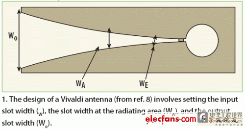
In addition to their efficiency and light weight, TSAs like the Vivaldi antenna are attractive because they can operate over a wide bandwidth, produce symmetrical end-fire beams, have good gain, and have low side lobes. Figure 1 shows the basic structure of a Vivaldi antenna, where WE is the input slot width, WA is the radiating slot width, and WO is the output slot width. The Vivaldi antenna has two propagation and radiation zones:
1. The area defined by WE< W< WA.
2. The area defined by WA < W{ < WO.
The Vivaldi antenna is a "surface-shaped" traveling wave antenna. The electromagnetic wave is transmitted along the antenna's curved slot path. The separation between the conductors is small compared to the free space wavelength and the wave is severely confined. As the separation increases, the confinement becomes weaker and the wave is emitted from the antenna. This occurs when the edge separation is greater than half a wavelength.
Traveling waves propagate along the structure of the Vivaldi antenna because the phase velocity of electromagnetic waves is less than the speed of light in free space. Therefore, the Vivaldi antenna is characterized by end-fire radiation, as shown in Figure 2. The phase velocity-limited case is related to the air dielectric case, so the beamwidth and sidelobe level are much larger than the existing dielectric substrate case. In addition, the phase velocity and guided wavelength vary with thickness, dielectric constant, and gradient design.

TSAs can be designed in a variety of tapered forms. Planar TSAs have two common features: the radiating slot serves as the antenna ground plane and the antenna is fed by a balanced slotline. Challenges in designing a planar TSA include using a low dielectric constant substrate material in the antenna and achieving proper slotline impedance matching. By using a low dielectric constant substrate material, a relatively high slotline impedance can be obtained. Thus, if a microstrip feed is used, it is difficult to achieve impedance matching. Therefore, the transition from microstrip to slot will limit the operating bandwidth of the TSA.
Experimental studies have been conducted to investigate the effect of bending of the support material on different types of TSAs. Experiments have shown that gradual bending has a significant effect on gain, beamwidth, and TSA bandwidth. In practice, the feed generally determines the high frequency limit, while the aperture size determines the low frequency limit. Therefore, to maximize the bandwidth of a TSA, a properly designed feed structure is critical. Although microwave integrated circuits (MICs) are generally implemented in microstrip, slotlines are still the best transmission medium for TSA feeding. The transition from microstrip to slotline should be compact and lossy in order to couple the microwave signal from the antenna to the planar microstrip circuit. A variety of feeding techniques can be used, the most common methods being coaxial feedlines and microstrip feedlines.
The advantages of choosing the microstrip-to-slotline transition for the Vivaldi antenna will be explained in detail in the next part of this series of articles.
The previous part of this series of articles explained how the Vivaldi antenna provides excellent directional propagation at microwave frequencies. This article will explain the advantages of using the microstrip to slotline transition in the Vivaldi antenna.
The transition from microstrip to slotline has many advantages over other feeding mechanisms. This transition can be easily fabricated using conventional photolithography processes. In addition, a double-sided printed circuit board (PCB) can be fabricated with microstrip on one side and slotline on the other side to achieve a compact transition. This type of transition is used in the Vivaldi antenna in this report (Figure 3).
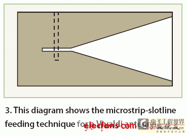
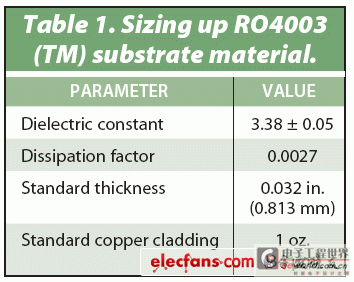
Microstrip lines widely used in microwave PCBs are unbalanced lines, although the Vivaldi antenna requires feeding with a slotted transmission line, which is a balanced line. The balun required for unbalanced to balanced transmission must operate at least twice the frequency range, and even up to multiple octaves. Preferably, the balun is independent of frequency. To illustrate the effectiveness of the TSA design, the Vivaldi antenna was chosen from other possible designs because a lot of research has been done on this configuration. Regardless of the antenna design, the choice of dielectric substrate material is critical. There are many substrate materials available, and their properties and dielectric constants vary greatly. This experimental Vivaldi antenna is more suitable for making transitions and Vivaldi antennas on low dielectric constant substrates to avoid the use of short drilled holes. This experimental antenna was made using RO4003C substrate material from Rogers Corporation (www.rogerscorporation.com), which has a dielectric constant of 3.38. Agilent's ADS software was used to optimize the design for 8GHz to 12GHz.
The Vivaldi antenna chose to use a microstrip-to-slotline transition because it has many advantages over other approaches. A major advantage is that the transition can be easily fabricated using conventional photoetching techniques, allowing for a double-sided PCB with microstrip on one side and slotline on the other.
Kayani et al. proposed a simple integrated Vivaldi antenna in 2005. Its single-sided design uses stripline to slotline coupling, as shown in Figure 4. The biggest advantage of this design is that it can be smaller than the anti-heel Vivaldi antenna. In addition, because the antenna size is small, the simulation time is relatively short when using computer-aided design (CAE) software tools. Figure 4 is a schematic diagram of a double-sided Vivaldi antenna operating at 8GHz to 12GHz, with a length of 7.48cm and a width of 2.08cm. The width of the microstrip line is 0.29cm. The diameter of the circular slot end is 1cm, and the slot line gap is 0.08cm.

1. Build a high-frequency Vivaldi antenna physical layer design
2. Select the ideal Momentum operating mode for Vivaldi antenna simulation
3. Determine the required substrate material and its characteristics
4. Calculate the substrate parameters based on the substrate material used in the previous calculation
5. Design the antenna port and define its characteristics
6. Create and generate circuit network
7. Build and simulate the performance of the Vivaldi antenna
8. View S-parameter and radiation pattern results.
The actual steps for building and simulating the Vivaldi antenna using Momentum software will be detailed in the next part of this series of articles, which will be published in the August 2008 issue of Microwaves & RF magazine. In the third part, a comparison of the Vivaldi antenna's measured results at 9 GHz using commercial test equipment and simulation results using Agilent Momentum planar EM simulation software will be presented.
The Vivaldi antenna can provide excellent directional propagation performance in the microwave band. As introduced in the first two parts of this article, the Vivaldi antenna can be a simple design based on the tapered slot antenna (TSA) architecture. As the third part of this article, the actual measurement results of the manufactured X-band antenna of this design are compared with the simulation results made by the Advanced Design System (ADS) software provided by Agilent Technologies (www.agilent.com).
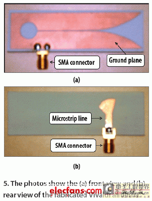
The eight-point design and simulation process using the Agilent Momentum EM analysis tool in the Agilent ADS software suite is described in detail in Part 1. The antenna is fabricated on RO4003C material, with the SMA edge connector bonded to the antenna's microstrip line, the outer ground pin of the SMA socket shorted to the antenna's slotted ground plane, and the center pin of the SMA soldered to the microstrip transmission line. Figure 5 shows the Vivaldi antenna board fabricated in this way, which is ready for testing and evaluation.
The measurement includes generating S parameters and radiation patterns. Figure 6 is an example of the test setup used to evaluate the S11 parameters of the Vivaldi antenna. Before taking measurements, the vector network analyzer (VNA) must be calibrated. The 50Ω connector of the Vivaldi antenna and the port 1 connector of the VNA are then connected via a 50Ω low-loss coaxial cable. The VNA measurement frequency range is set to 8 to 12 GHz.
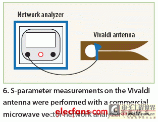
Once the S11 log magnitude values are obtained from the VNA, they can be compared to the simulated results obtained from the Momentum analysis. This comparison shows that the optimal frequency for the radiation pattern measurements is 9.20 GHz. The test setup for the radiation pattern measurements is shown in Figure 7. To perform these measurements, a microwave signal generator is connected to the SMA connector of the Vivaldi antenna through a high-quality 50Ω coaxial cable. The signal generator is tuned to the optimal frequency of the antenna, 9.20 GHz, and its output power level is set to +10 dBm. If this is the correct optimal frequency for the antenna, then the measured radiation pattern should match the simulation results.
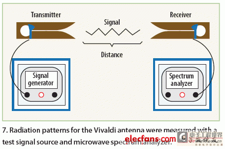
A microwave spectrum analyzer with a suitable frequency range as the measurement receiver is connected to the other Vivaldi antenna via a low-loss 50Ω coaxial cable and then tuned to the frequency range used by the signal generator (8 to 12 GHz).
In order to test the Vivaldi antenna transmitter and receiver simultaneously, the distance between the transmitter and receiver should be set to 1 meter or more. The receiving antenna can be rotated to different angles, while the transmitting antenna is set at a fixed angle. This setup is very beneficial for measuring the power received by the Vivaldi antenna and determining the polar field radiation pattern of the antenna. The receiving antenna can be rotated arbitrarily from 0 to 360 degrees in 10 degree steps, and the power level measured on the spectrum analyzer is in dBm. The power transmitted by the Vivaldi antenna can be obtained by replacing the horn and parabolic transmitting antenna with the Vivaldi antenna as the transmitter.
The gain measurement test setup is the same as the radiation pattern measurement. The horn antenna is connected to a signal generator via a precision 50Ω coaxial cable and used as a transmitter. The signal generator frequency is set to 9.20GHz and the power level is set to 0dBm. The Vivaldi antenna is connected to the spectrum analyzer via a coaxial cable, and the horn antenna is pointed at the Vivaldi antenna. The power received by the Vivaldi antenna is displayed on the spectrum analyzer display, and the gain can be calculated based on this power value.
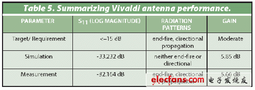
As mentioned above, the main measured parameters of the Vivaldi antenna include S parameters, radiation pattern and gain. As suggested by Langley et al. in 199612, the S11 log magnitude should be less than -15dB for optimal antenna performance. The radiation pattern of a properly designed Vivaldi antenna should show an end-fire radiation pattern with directional propagation characteristics. The antenna should have a moderate gain to have high transmission efficiency in microwave imaging applications.
The final part of this article series will explore what factors affect the measurements of the Vivaldi antenna.
Part 3 of this series compares actual measurements of a manufactured X-band antenna with simulations using Advanced Design System (ADS) software from Agilent Technologies (www.agilent.com). We conclude by exploring factors that affect the measurements of the Vivaldi antenna.
Figure 8 plots the measured S11 results (log magnitude in dB versus frequency) and compares them to the ADS simulation results. As can be seen from the figure, the simulation results and the measured values match very well. Any differences in the two figures may be due to the mismatch between the cable and the antenna input, as this was not accounted for in the simulation. During simulation, the input port was located at the edge of the substrate. However, in the actual measurement, the SMA connector was soldered to the inside of the antenna substrate, so the actual transmission line was shorter than the one used in the simulation.
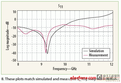
Table 2 lists the measured and simulated results for the S11 log magnitude performance of the Vivaldi antenna. The frequency of interest is 9.20 GHz, where both the simulated and measured S11 log magnitude are below -30 dB. Comparing the simulated and measured results at the minimum point, the S11 log magnitude performance is below -40 dB. This indicates low reflection losses with the transmitted signal being almost completely received by the antenna. Any differences at 9.20 GHz may be due to manufacturing quality, although this design can tolerate these minor differences.

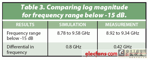
Table 3 compares the simulated and measured data for S11 log magnitude below -15dB in the above frequency range. The data shows that the antenna has a wide frequency range and the design works well at 9.20GHz as both the simulated and measured S11 values are less than -15dB.
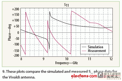
Some differences in the simulated and measured S11 phases were found in this Vivaldi antenna design (Figure 9). The simulation showed only one phase change, while the measured data showed three phase changes. A slight phase shift occurred between 9.10 and 9.30 GHz. At 9.20 GHz, the simulated phase result was -77.738 degrees, while the measured result at the same frequency was 49.710 degrees, a difference of 127.448 degrees.
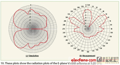
The simulated and measured radiation patterns of the Vivaldi antenna at 9.20 GHz are shown in Figure 10, which also shows some differences. The simulation results show that the antenna does not radiate in a directional manner, while the measurement results show that it radiates in a directional manner and the radiation is high when the antenna and the transmitter are facing each other. The measured radiation pattern is the same as the end-fire pattern, so it is more accurate in theory.
There are many factors that affect measurements on Vivaldi antennas, including:
1. Excessive solder used to connect the Rogers RO4003C dielectric material and the SMA type connector. Excessive solder may increase conductivity and change the surface current.
2. Certain interferences and obstacles may occur between the Vivaldi antenna and the transmitter during the radiation pattern measurement, which will prevent the effective transmission of the radiated energy.
3. Since the measurement is not done in free space, some environmental elements may absorb the emitted energy.
4. Any degradation in the manufacturing quality of the RO4003C dielectric material will affect the test results.
5. The electrical wires or coaxial cables used with the spectrum analyzer may also cause measurement instability.
By calculating the gain in dB, the radiation efficiency of the antenna and the efficiency of the entire antenna system can be evaluated. Table 4 compares the simulated and measured gains. Many factors affect the gain, including the materials used to build the antenna, the physical dimensions and properties of the materials, the antenna components, and the method of assembling them.

In summary, the simulation and measurement results show that the designed Vivaldi antenna can provide good performance at X-band, especially at 9.20 GHz. The design requirements of the antenna can be fully met, as summarized in Table 5.
Previous article:Electromagnetic and mathematical software for RF/microwave design
Next article:Design of embedded-fed microstrip patch antenna
- Popular Resources
- Popular amplifiers
- High signal-to-noise ratio MEMS microphone drives artificial intelligence interaction
- Advantages of using a differential-to-single-ended RF amplifier in a transmit signal chain design
- ON Semiconductor CEO Appears at Munich Electronica Show and Launches Treo Platform
- ON Semiconductor Launches Industry-Leading Analog and Mixed-Signal Platform
- Analog Devices ADAQ7767-1 μModule DAQ Solution for Rapid Development of Precision Data Acquisition Systems Now Available at Mouser
- Domestic high-precision, high-speed ADC chips are on the rise
- Microcontrollers that combine Hi-Fi, intelligence and USB multi-channel features – ushering in a new era of digital audio
- Using capacitive PGA, Naxin Micro launches high-precision multi-channel 24/16-bit Δ-Σ ADC
- Fully Differential Amplifier Provides High Voltage, Low Noise Signals for Precision Data Acquisition Signal Chain
- Innolux's intelligent steer-by-wire solution makes cars smarter and safer
- 8051 MCU - Parity Check
- How to efficiently balance the sensitivity of tactile sensing interfaces
- What should I do if the servo motor shakes? What causes the servo motor to shake quickly?
- 【Brushless Motor】Analysis of three-phase BLDC motor and sharing of two popular development boards
- Midea Industrial Technology's subsidiaries Clou Electronics and Hekang New Energy jointly appeared at the Munich Battery Energy Storage Exhibition and Solar Energy Exhibition
- Guoxin Sichen | Application of ferroelectric memory PB85RS2MC in power battery management, with a capacity of 2M
- Analysis of common faults of frequency converter
- In a head-on competition with Qualcomm, what kind of cockpit products has Intel come up with?
- Dalian Rongke's all-vanadium liquid flow battery energy storage equipment industrialization project has entered the sprint stage before production
- Allegro MicroSystems Introduces Advanced Magnetic and Inductive Position Sensing Solutions at Electronica 2024
- Car key in the left hand, liveness detection radar in the right hand, UWB is imperative for cars!
- After a decade of rapid development, domestic CIS has entered the market
- Aegis Dagger Battery + Thor EM-i Super Hybrid, Geely New Energy has thrown out two "king bombs"
- A brief discussion on functional safety - fault, error, and failure
- In the smart car 2.0 cycle, these core industry chains are facing major opportunities!
- Rambus Launches Industry's First HBM 4 Controller IP: What Are the Technical Details Behind It?
- The United States and Japan are developing new batteries. CATL faces challenges? How should China's new energy battery industry respond?
- Murata launches high-precision 6-axis inertial sensor for automobiles
- Ford patents pre-charge alarm to help save costs and respond to emergencies
- Summary: Reading notes on "Operational Amplifier Parameter Analysis and LTspice Application Simulation"
- How to use CPLD to collect asynchronous signals
- TLP3547 Evaluation Board Preliminary Evaluation Report
- Share: Where should the inductor be placed on the power supply PCB?
- [Open Source] GPIO Experiment Tutorial - Crazy Shell ARM Dual Processor Development Board Series
- Does the embedded industry strictly restrict college education?
- BAW filters help 5G achieve high-quality communications and higher efficiency
- [RISC-V MCU CH32V103 Review] Hardware IIC drive OLED (finally)
- ADC10 multi-channel input of msp430g2553
- 【TI Recommended Course】#Texas Instruments Field Transmitter Output Interface/Fieldbus Solution#

 MATLAB and FPGA implementation of wireless communication


 京公网安备 11010802033920号