However, if the design is slightly complicated, then too much attention to the underlying details will become a burden.
Imagine that we usually write C programs on the computer, such as outputting a line of words on the display, we only need to use a printf() sentence to complete it. As for how the print command is transmitted to the display chip, which chip pin changes, and how it is transmitted to the display for output, and other issues involving the underlying hardware, we don’t need to pay too much attention. Therefore, we call the work of describing the design logic with high-level languages such as printf() software design. Obviously, software is just an abstract invisible and intangible thing, and its structure is close to the logic of human thinking. No matter how ingenious the software is, it can only be reflected in the hardware.
When developing computer applications, the hardware is ready-made, and the bridge between software and hardware has long been built by the operating system. We only need to concentrate on completing the conception and design of the software.
Obviously, the division of labor between software and hardware will bring great convenience to electronic design. Naturally, some people have introduced this division of labor into the field of FPGA design, thinking about how to do a hardware-software collaborative design on a small FPGA, with those responsible for hardware design and those responsible for software performing their respective duties, and finally integrating them together to double the efficiency.
Let's see how nios does it. Take out the DE2 development board, which has many peripheral interfaces and chips connected to it. That is the hardware. There is a large CycloneII chip in the middle, which is empty and waiting for us to write programs and download them to run. In the previous article, we used the most primitive method to write a digital tube controller. This time we will use a different method. The same digital tube controller is completed by hardware-software collaborative design.
Compared with computers, we have the hardware, so the software is written in C language, but the nios system does not provide WinXP, which means that the bridge between software and hardware has to be solved by ourselves.

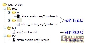
As shown in the figure above, the bridge is divided into three layers: hardware control layer, device driver layer, and hardware abstraction layer (HAL). Since it is the transitional part between software and hardware, the design of these three layers requires a certain degree of understanding of both hardware and software. Let's call it "software and hardware mixed design".
The task to be completed by each layer is to integrate and simplify the hardware operation details, integrate, and integrate again to make it clear at a glance.

<1> Hardware control layer
The hardware control layer is the one that deals directly with the hardware.
As mentioned above, the purpose of building a "bridge" is to allow software designers to completely ignore the hardware operation details. Therefore, we hope that all hardware details can be solved at this layer and provide a neat "interface" to the device driver layer. The previous example can be seen as the prototype of the hardware controller, but it still lacks an interface with the device driver layer.
What is "neat"? For example, when designing a digital tube controller, I want it to display the number "5". The best way is to pass the data "5" and the command representing "display" from the device driver layer to the hardware control layer, and directly tell it: I want "digital tube" "display" "5". As for which pin level should be controlled to display "5", it is all the responsibility of the hardware control layer.
Examples of division of labor and cooperation are common in daily life. For example, the post office wants to send a letter to Zhang San who lives in Community A. The postman puts the letter in the mailbox of Community A, and the community property management confirms Zhang San's specific residence and finally delivers the letter to Zhang San.
By analogy, the post office is equivalent to the device driver, the property management is equivalent to the hardware manager, and Zhang San is the specific hardware. The interface between the post office and the property management is the mailbox provided by the property management. The interface between the device driver and the hardware management layer, which we call "register", is also provided by the hardware management layer. "Register" is the key to the clear division of labor and mutual connection between the two layers.
In the eyes of device driver developers, hardware is an abstraction of a set of registers, which indirectly control hardware behavior by reading and writing registers.
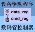
Then, add a data register and a command register to the digital tube controller:
data_reg stores the data to be displayed, and cmd_reg is displayed when it is '1' and cleared when it is '0'.

<2> Avalon bus
You may say, what's the big deal? Just establish a channel between each hardware manager and device driver. This is the most direct way, but it is obviously not the best way. Just think about it, why do cities build highways? Wouldn't it be possible to drive cars if we built dozens of narrow roads? Someone answered: To collect road fees. $%@&&! Driving on narrow roads is slow, and management and coordination is a big problem. Is it easier to manage a large highway or dozens of narrow roads?
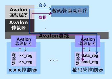
Well, back to the point, the nios system needs a "highway", called a "bus", and the "bus arbitrator" plays the role of a "traffic management bureau", controls the entry and exit of data, and provides an interface for each hardware to enter and exit the "highway", using an "address" to identify the location of this interface. nios uses the Avalon bus, which has a set of interface specifications:
synchronous clock clk
chip select signal chipselect
address address
read request read
read transfer readdata
write request write
write transfer writedata
These are the more important interface signals, and the others are not listed one by one. To access the bus, the hardware controller must follow the interface specification, just like a toll booth must be set up at the exit of the highway.

Then add Avalon bus signals to the digital tube controller:

Since two registers and avalon signals are added, it is necessary to make necessary changes to the hardware logic. The general process is that when chipselect and write are valid, write_data is assigned to the register corresponding to address; when chipselect and write are valid, the value of the register corresponding to address is assigned to read_data. In addition, the digital tube output signal oSEG0 is determined according to the contents of these two registers. The code is not posted here, please see the project compressed package for details.
<3> Device driver
In fact, the "bus arbitrator" can also be regarded as a hardware controller, but it is not responsible for specific hardware, but for data transmission. Then it also has its own device driver, which encapsulates the details of bus operation. Since the bus is ready-made, we adhere to the principle of "take it as it is", no matter how it is implemented, as long as we can use it.
For example, the digital tube device driver needs to pass the data "5" and the "display" command to the digital tube controller, and design two functions. Since the transmission of data and commands must pass through the bus, the bus driver function IOWR (base address, offset, data) needs to be called. In addition, IORD (base address, offset) is used to read the register. These two functions are in
The path of
At this point, the "bridge" is built.

The function is easy to understand literally. When defining the two registers just now, data_reg is in the front, so the offset is 0, and cmd_reg is in the back, and the offset is 1. ××_REG_MSK is called a mask. The Avalon bus data interface has 32 bits in total, but the data_reg bit width we designed is 3 and the cmd_reg bit width is 1. The mask is used to tell the register width. It is not actually needed. ××_REG_OFST is the offset in the register. It is also not needed here. Let's write it first.
OK, our digital tube device driver file is officially released. See if it is much simpler and clearer?
<4> The hardware abstraction layer (HAL)
device driver encapsulates only a read and write operation of a register, and has a single function. It needs to be encapsulated again in the hardware abstraction layer.
It is clear to list these functions directly, and no extra explanation is needed.

At this point, the "bridge" is built.
Next, add our "digital tube controller" to the SOPC Builder system.
Now almost all books on NIOS will mention custom user peripherals, and they all use the example PWM provided by Altera. The "digital tube controller" in this article is modified according to it. Haha, I am ashamed of it. The reason why I want to change it is that, first, it uses Verilog instead of VHDL, and most people first contact VHDL; second, the display effect of PWM does not seem to be very obvious, and changing it to a digital tube display is relatively more fulfilling; third, the logic of PWM is a little bit complicated. Our focus is to explain how to customize peripherals. Of course, the simpler the example, the better.
Since the modification is based on the original PWM, the structure of the project in this article is highly consistent with it, and the steps to add it to the sopc builder are similar. I will not write any more words here, and you can do it according to the book:
"SOPC Embedded System Basic Tutorial (Zhou Ligong et al.)" Chapter 8...
Next, build a nios system including a "digital tube controller" and write an application to count from 0 to 9.
Post an official nios design flow chart, it looks very beautiful, right? It is worthy of being an altera product, large and complete without being messy.

Let's talk about the "SOPC Builder" in the middle first. Its task is to build a nios system that "uses Nios CPU as the core and Avalon bus as the link to connect various hardware devices"; this system must run in FPGA, so it must be attached to a Quartus II project, and use the Quartus II on the left to allocate pins and other tasks to generate a hardware system; then, the Nios II IDE on the right can design applications on this hardware system; finally, download the hardware system and software program to the FPGA chip respectively, and you are done.
Below is the step by step
<1> Create a new project in Quartus II, and name it "DE2_SEG7".
<2> "Tool" → "SOPC Builder" Open SOPC Builder.
<3> "System Name": nios2_system Select VHDL.
A minimum system that includes a "digital tube controller" consists of at least 3 parts: the CPU is indispensable, the RAM stores the code, and the "seg7_avalon" just designed.
<4> Add "Nios II Processor" and select "Nios II/e". The simplified version is enough.
<5> Add "On-Chip Memory", select "RAM" for type, the default bit width is "32 bits", and select "48Kbytes" for "Total Memory". The software will take up more than 40K space later.
<6> Add "seg7_avalon".
<7> Change the names of these three components to look better, then set the base address of RAM to "0x00000000", and then right-click to lock the base address, as shown in the figure:

Why should the base address of RAM be locked to 0? Click the second tab, and you can see that "Reset Address" corresponds to RAM. The system reset must start from address 0.

<8> Since the address allocation was manually changed and messed up just now, let the system automatically allocate it again. Of course, the locked base address of RAM will not change. "System" →"Auto-Assign Base Addresses". The final system component list is as follows:

Note that the address range of seg7 is "0x00010800"→"0x00010807", occupying 8 addresses. The addresses of the nios system are allocated by bytes, that is, each byte occupies one address. Two registers are defined in the digital tube controller. The avalon bus stipulates that each register occupies 32 bits (it doesn't matter whether it is actually 32 bits, anyway, it is allocated according to the maximum 32 bits). In this way, the two registers occupy a total of 8 bytes, so naturally 8 addresses are required.
<9> Click "Generate" to generate the nios system and return to Quartus II.
<10> Create a top-level file "File" → "New" → "Block Diagram/Schematic File", import the nios II system, and add input and output pins. Then, "Assignment" → "Import Assignment", add the pin assignment file (DE2_tutorialsdesign_files DE2_pin_assignments.csv in the DE2 CD directory), and change the pin name of the top-level file to make it consistent with the .csv file.

<11> Compile and check the compilation report. It can be seen that the 48K RAM occupies 83% of the memory bits of the chip, which is almost used up.

<12> The hardware part has been completed, close Quartus II, open Nios II IDE, and switch to the working directory.
<13> "File" → "New" → "C/C++ Application", "SOPC Builder System" select "nios2_system.
ptf" (that is, the stuff generated by Generate Nios II system just now), then select the template "Hello World" (purely lazy), change the "name" at the top to "seg_example", "Finish".
<14> Modify hello_world.c. The functions of the code are: initialize the digital tube first, wait for 2 seconds, and then loop from 0 to 9, with a 2-second screen clearing during the loop. The macro definition of SEG7_BASE is in system.h, which is actually the base address 0x00010800 of seg7_avalon in SOPC Builder.

<15> "Project" → "Build Project", get the compilation report, the software occupies 7K space...

<16> Download it to the DE2 board, run it, and the digital tube keeps flashing.
OK, the one-stop service from hardware to software is finished.
Previous article:Easy-to-understand modelsim learning notes
Next article:EDA technology design scheme for electronic password lock
Recommended ReadingLatest update time:2024-11-17 03:06
- Popular Resources
- Popular amplifiers
- High signal-to-noise ratio MEMS microphone drives artificial intelligence interaction
- Advantages of using a differential-to-single-ended RF amplifier in a transmit signal chain design
- ON Semiconductor CEO Appears at Munich Electronica Show and Launches Treo Platform
- ON Semiconductor Launches Industry-Leading Analog and Mixed-Signal Platform
- Analog Devices ADAQ7767-1 μModule DAQ Solution for Rapid Development of Precision Data Acquisition Systems Now Available at Mouser
- Domestic high-precision, high-speed ADC chips are on the rise
- Microcontrollers that combine Hi-Fi, intelligence and USB multi-channel features – ushering in a new era of digital audio
- Using capacitive PGA, Naxin Micro launches high-precision multi-channel 24/16-bit Δ-Σ ADC
- Fully Differential Amplifier Provides High Voltage, Low Noise Signals for Precision Data Acquisition Signal Chain
- Innolux's intelligent steer-by-wire solution makes cars smarter and safer
- 8051 MCU - Parity Check
- How to efficiently balance the sensitivity of tactile sensing interfaces
- What should I do if the servo motor shakes? What causes the servo motor to shake quickly?
- 【Brushless Motor】Analysis of three-phase BLDC motor and sharing of two popular development boards
- Midea Industrial Technology's subsidiaries Clou Electronics and Hekang New Energy jointly appeared at the Munich Battery Energy Storage Exhibition and Solar Energy Exhibition
- Guoxin Sichen | Application of ferroelectric memory PB85RS2MC in power battery management, with a capacity of 2M
- Analysis of common faults of frequency converter
- In a head-on competition with Qualcomm, what kind of cockpit products has Intel come up with?
- Dalian Rongke's all-vanadium liquid flow battery energy storage equipment industrialization project has entered the sprint stage before production
- Allegro MicroSystems Introduces Advanced Magnetic and Inductive Position Sensing Solutions at Electronica 2024
- Car key in the left hand, liveness detection radar in the right hand, UWB is imperative for cars!
- After a decade of rapid development, domestic CIS has entered the market
- Aegis Dagger Battery + Thor EM-i Super Hybrid, Geely New Energy has thrown out two "king bombs"
- A brief discussion on functional safety - fault, error, and failure
- In the smart car 2.0 cycle, these core industry chains are facing major opportunities!
- Rambus Launches Industry's First HBM 4 Controller IP: What Are the Technical Details Behind It?
- The United States and Japan are developing new batteries. CATL faces challenges? How should China's new energy battery industry respond?
- Murata launches high-precision 6-axis inertial sensor for automobiles
- Ford patents pre-charge alarm to help save costs and respond to emergencies
- Some cases of DSP program crash (flying away) - hardware reasons
- 39 yuan purchase or free: RCSN's wireless serial port tool is coming~
- The world's largest computer chip
- [National Technology N32 MCU Development Package] --N32G457 Series
- Using ir2110 driver to make a buck circuit
- Methods for solving faults in FPGA design and development based on EDA simulation technology.pdf
- Tuya Sandwich Wi-Fi & BLE SoC NANO Main Control Board WBRU+ Simple Development (Zero Code Solution)
- Belling Products MEQ6310 Low Dropout Low Noise Voltage Regulator
- Desktop assistant based on GD32F350 - Part 1
- Super brain-burning question, about electric fishing? !

 Principles and Applications of Wireless Sensor Networks (Tang Hong)


 京公网安备 11010802033920号