Design requirements:#
Write a driver for the matrix keyboard
Press the corresponding keys respectively. The digital tube will accumulate the corresponding values of the keyboard and display
Design Overview:
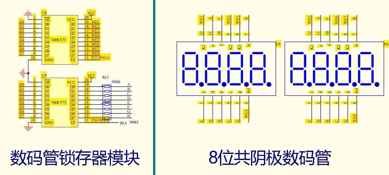
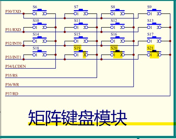
According to the design requirements, the required single-chip microcomputer chip is STC89C52, and the hardware tool used is an intelligent car based on STC89C52 developed by Huaqing Yuanjian. The car is equipped with the required matrix key module and digital tube module. The matrix key module is controlled by P3 port, the digital tube module bit selection is controlled by P2.7 port, the segment selection is controlled by P2.6 port, and the digital display is controlled by P0 port. STC89C52 is a low-power, high-performance 8-bit microcontroller, which is an enhanced version of the 80C51 single-chip microcomputer.
Matrix keyboard: 4x4 matrix keyboard has 16 keys. The left end of each key is connected to a line to form a row line, and the right end of each key is also connected to a line to form a column line. The lower 4 bits of P3 port are connected to the row line, and the upper 4 bits are connected to the column line. The keys in the matrix keyboard are accurately identified by scanning the level changes at both ends of the keys.
source code:#
#include
#define uint unsigned int
#define uchar unsigned char
sbit WELA = P2^7; //define bit select IO port
sbit DULA = P2^6; //define segment select IO port
void matrix_key_scan();
void delay_ms(uint ms);
void sum_key();
void display_num(unsigned int num);
void display_digit(unsigned char wela,unsigned char dula);
uint key_value = 0; //Define global variables to save key values
uint keynum1 = 0;
uint keynum2 = 0;
//Digital tube 0-9 segment selection code
uchar code Du[] = {0x3f,0x06,0x5b,0x4f,
0x66,0x6d,0x7d,0x07,
0x7f,0x6f};
/*-----Matrix keyboard scanning function-----*/
void matrix_key_scan()
{
uchar temp;
uchar a = 0;
P3 = 0x0f; // Pull all row levels high and column levels low to perform row scanning
temp = P3;
if(temp != 0x0f) // Check if a key is pressed
{
delay_ms(5); //delay debounce
if(temp != 0x0f) // confirm the button is pressed again
{
P3 = 0x0f; // Pull all row levels high and column levels low to perform row scanning
temp = P3;
switch(temp)
{
case 0x0e:key_value = 0; //Line 1
break;
case 0x0d:key_value = 4; //Line 2
break;
case 0x0b:key_value = 8; //Line 3
break;
case 0x07:key_value = 12; //Line 4
break;
}
P3 = 0xf0; //Pull all column levels high and row levels low to scan columns
temp = P3;
switch(temp)
{
case 0xe0:key_value = key_value + 0; //Column 1
break;
case 0xd0:key_value = key_value + 1; // Column 2
break;
case 0xb0:key_value = key_value + 2; //Column 3
break;
case 0x70:key_value = key_value + 3; // Column 4
break;
//Here a delay of 200ms is required because the matrix keyboard scanning function is continuously executed in the while loop
//If you do not release the key after pressing it or release it slowly, the keynum2 variable will continue to accumulate,
delay_ms(200);
keynum1 = key_value;
keynum2 = keynum2 + keynum1;
}
}
while((a < 50)&&(temp != 0xf0))//Wait for the key to be released
{
a++;
}
}
/*-----Millisecond delay function-----*/
void delay_ms(uint ms)
{
volatile uint i,j;
for(i = ms;i > 0;i--)
{
for(j=0;j<110;j++);
}
}
/*--------Digital tube display digital function---------*/
void display_num(unsigned int num)
{
unsigned int div = 0;
unsigned char rema = 0;
unsigned char index = 0;
while((div = num / 10) > 0)
{
rema = num % 10;
display_digit(index,rema);
num = div;
index++;
delay_ms(2);
}
rema = num % 10;
display_digit(index,rema);
}
/*-------Digital tube position selection function-------*/
void display_digit(unsigned char wela,unsigned char dula)
{
WELA = 1; // The bit select latch is set high and data is sent
P0 = 0xFF; //Erasing
P0 &= ~(1 << (7 - wela));//1000 0000 0111 1111
WELA = 0; // Set the bit select latch low to save data
DULA = 1; // The segment select latch is set high and data is sent
P0 = Du[dula]; //Send data
DULA = 0; // The segment select latch is set low to save data
}
void main()
{
while(1)
{
matrix_key_scan();
display_num(keynum2);
}
}
Schematic diagram of the car: #
Previous article:Software simulation to implement the iic protocol (51 as an example)
Next article:Fan based on STC51 microcontroller
Recommended ReadingLatest update time:2024-11-16 09:54

- Popular Resources
- Popular amplifiers
 Professor at Beihang University, dedicated to promoting microcontrollers and embedded systems for over 20 years.
- Innolux's intelligent steer-by-wire solution makes cars smarter and safer
- 8051 MCU - Parity Check
- How to efficiently balance the sensitivity of tactile sensing interfaces
- What should I do if the servo motor shakes? What causes the servo motor to shake quickly?
- 【Brushless Motor】Analysis of three-phase BLDC motor and sharing of two popular development boards
- Midea Industrial Technology's subsidiaries Clou Electronics and Hekang New Energy jointly appeared at the Munich Battery Energy Storage Exhibition and Solar Energy Exhibition
- Guoxin Sichen | Application of ferroelectric memory PB85RS2MC in power battery management, with a capacity of 2M
- Analysis of common faults of frequency converter
- In a head-on competition with Qualcomm, what kind of cockpit products has Intel come up with?
- Dalian Rongke's all-vanadium liquid flow battery energy storage equipment industrialization project has entered the sprint stage before production
- Allegro MicroSystems Introduces Advanced Magnetic and Inductive Position Sensing Solutions at Electronica 2024
- Car key in the left hand, liveness detection radar in the right hand, UWB is imperative for cars!
- After a decade of rapid development, domestic CIS has entered the market
- Aegis Dagger Battery + Thor EM-i Super Hybrid, Geely New Energy has thrown out two "king bombs"
- A brief discussion on functional safety - fault, error, and failure
- In the smart car 2.0 cycle, these core industry chains are facing major opportunities!
- The United States and Japan are developing new batteries. CATL faces challenges? How should China's new energy battery industry respond?
- Murata launches high-precision 6-axis inertial sensor for automobiles
- Ford patents pre-charge alarm to help save costs and respond to emergencies
- New real-time microcontroller system from Texas Instruments enables smarter processing in automotive and industrial applications
- Building ESP32-C3 development environment based on window Visual Studio Code: ESP-IDF
- [AT-START-F403A Review] + Unsuccessful W25Q128 Read and Write
- I don't know much about the commonly used domestic device manufacturers.
- Cadence Allegro beginners must read
- [Atria Development Board AT32F421 Review] 1. Unboxing and lighting
- EEWORLD University ---- Introduction to CC2650MODAPluetooth? Low-energy RF module
- Thank you for having me + EE has brought me so much knowledge this year! + Thank you to my family for their support and love! + Thank you to my colleagues and friends for their generous help along the way!
- After the microcontroller is powered on, it runs a display program and encounters a very strange problem.
- A brief discussion on LTE technology and practical application solutions
- SD/TF card usage issues


 Principles and Applications of Single Chip Microcomputers 3rd Edition (Zhang Yigang)
 STC51 MCU Program and Simulation Exercises


 京公网安备 11010802033920号