In the last class, we already know that the symbols R7 and R6 in the program represent RAM units, which are used to store some data. Now let’s take a look at the meaning of other symbols.
DELAY: MOV R7, #250; (6) D1: MOV R6, #250; (7) D2: DJNZ R6, D2; (8) DJNZ R7, D1; (9) RET ;(10) |
|
〈MCU Delay Program〉
MOV: This is an instruction, which means to transfer data. Speaking of transfer, we all know that to transfer something, we need to transfer it from one person's hand to another person's hand, which means there must be a receiver, a transmitter and something. From the instruction MOV R7, #250, R7 is a receiver, 250 is the number to be transferred, and the transmitter is omitted in this instruction (note: not every transfer instruction will be omitted, in fact, most data transfer instructions will have a transmitter). Its meaning is also very clear: send the data 250 to R7, so after executing this instruction, the value in the R7 unit should be 250. There is a # sign in front of 250, what does this mean? This # is used to indicate that 250 is the thing itself that is being transferred, not the transmitter. So what does MOV R6, #250 mean? There should be no need to analyze it.
DJNZ: This is another instruction. Let's look at the two things following this instruction. One is R6 and the other is D2. We already know what R6 is. Let's check what D2 is. D2 is in front of this line. We have already learned that it is called a label. What is the purpose of a label? It is to give this line a name. The execution process of the DJNZ instruction is as follows. It subtracts 1 from the value of the first parameter behind it, and then checks to see if the value is equal to 0. If it is equal to 0, it will continue to execute. If it is not equal to 0, it will transfer to where? You may have guessed that it transfers to the place specified by the second parameter (please explain how this statement is executed in your own words). The final execution result of this instruction is to circle around 250 times.
After executing DJNZ R6, D2 (that is, after the value of R6 is equal to 0), the next line will be executed, that is, DJNZ R7, D1. Please analyze the result of this sentence by yourself. (Mov R6, #250 will be executed, and the value in R7 will be reduced by 1). Finally, DJNZ R6, D2 will be executed 250*250=62500 times. Why execute the same instruction so many times? It is to delay.
A question: What will happen if 0 is put in R6?
2. Timing Analysis:
We introduced the delay program earlier, but it is not perfect, because we only know that the sentence DJNZ R6, D2 will be executed 62500 times, but how long will it take to execute so many times? Does it meet our requirements? We don't know yet, so we will solve this problem below.
Let me first ask a question: What is the most important thing in our school? (Bell) The principal can go on business trips, and teachers can take a break, but if there is no bell in the school for a day, there will be chaos. The whole school works in unison and in a coordinated manner under the unified command of the bell. This bell rings according to a certain schedule, which we can call "time sequence - the order of time". A unit composed of people must have a certain time sequence, and computers must have a stricter time sequence. In fact, a computer is more like a big clock. There are strict rules for when the minute hand moves, when the second hand moves, and when the hour hand moves, and there can be no chaos at all. The things that computers have to accomplish are more complicated, so their time sequence is also more complicated.
We know that when a computer is working, it fetches instructions from the ROM one by one and then executes them step by step. We define the time it takes for a computer to access the memory as a machine cycle. This is a time reference, just like we humans use "seconds" as our time reference. Why not just use "seconds"? It's so good and very familiar. As we continue to learn, we will find that using "seconds" is not a habit.
A machine cycle consists of 12 clock cycles. Let's calculate how long a machine cycle is. Suppose a single-chip microcomputer works with a 12M crystal oscillator, and its clock cycle is 1/12 (microseconds). Its machine cycle is 12*(1/12) or 1 microsecond. (Please calculate the machine cycle of a single-chip microcomputer working with a 6M crystal oscillator).
Among all the instructions of the MCS-51 microcontroller, some are completed relatively quickly and only require one machine cycle, some are completed relatively slowly and require two machine cycles, and two instructions require four machine cycles. This is not difficult to solve, is it? The execution time of the instruction I asked you to sweep the floor is always longer than the instruction of wiping the blackboard. In order to keep the length of the instruction execution time constant, a new concept is introduced: instruction cycle. The so-called instruction cycle refers to the time to execute an instruction. INTEL gives the instruction cycle number for each instruction. Most of these data do not need to be remembered by us, but some instructions need to be remembered, such as the DJNZ instruction, which is a two-cycle instruction.
Let's calculate the delay. First, we must know the frequency of the crystal oscillator. If the crystal oscillator is 12M, then one machine cycle is 1 microsecond. The DJNZ instruction is a two-cycle instruction, so it takes 2 microseconds to execute once. A total of 62,500 executions is exactly 125,000 microseconds, or 125 milliseconds.
If you still don't understand the above sentences, please see the detailed explanation here: http://www.51hei.com/mcu/1247.html
For a detailed explanation of how to write a delay function in C language, please see: http://www.51hei.com/mcu/710.html
Exercise: Design a delay program with a delay of 100 milliseconds.
Key points analysis: 1. Whether the number in a unit can exceed 255. 2. How to allocate two numbers.
3. Reset Circuit
1. Reset method
⒈ Reset condition:
The RST pin maintains a high level for more than 2 machine cycles.
⒉ Reset circuit

⒊ CPU status after reset
PC: 0000H TMOD: 00H
Acc: 00H TCON: 00H
B: 00H TH0: 00H
PSW: 00H TL0: 00H
SP: 07H TH1: 00H
DPTR: 0000H TL1: 00H
P0~P3:FFH SCON:00H
IP: ×××00000B SBUF: Uncertain
IE: 0××00000B PCON: 0×××0000B
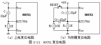
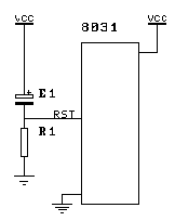
Any single-chip microcomputer must have a reset process before working. What does reset mean? It is like the preparatory bell we ring before class. When the preparatory bell rings, everyone automatically enters the classroom from the playground and other places. During this period of time, there is no teacher intervention. For the single-chip microcomputer, the program has not started to execute yet, and it is doing preparation work. Obviously, the preparation work does not take too long, and the reset only takes 5ms. How to reset? Just add a high level to the RST pin of the single-chip microcomputer. As mentioned above, the time is not less than 5ms. In order to achieve this requirement, many methods can be used. Here is a reference, see Figure 1. In fact, we have seen it in the figure of the last experiment.
The working principle of this reset circuit is: when the power is turned on, the two ends of the capacitor are equivalent to a short circuit, so the RST pin is at a high level, and then the power supply charges the capacitor through the resistor, the voltage at the RST end slowly drops to a certain level, that is, a low level, and the microcontroller starts to work normally.
Previous article:MCU simulation I2C bus and 24C02 (I2C EEPROM) reading and writing examples
Next article:Lesson 6: MCU parallel port structure
Recommended ReadingLatest update time:2024-11-15 13:23


- Popular Resources
- Popular amplifiers
-
 Wireless Sensor Network Technology and Applications (Edited by Mou Si, Yin Hong, and Su Xing)
 -
 Modern Electronic Technology Training Course (Edited by Yao Youfeng)
 -
 Modern arc welding power supply and its control
 -
 Small AC Servo Motor Control Circuit Design (by Masaru Ishijima; translated by Xue Liang and Zhu Jianjun, by Masaru Ishijima, Xue Liang, and Zhu Jianjun)
- Learn ARM development(16)
- Learn ARM development(17)
- Learn ARM development(18)
- Embedded system debugging simulation tool
- A small question that has been bothering me recently has finally been solved~~
- Learn ARM development (1)
- Learn ARM development (2)
- Learn ARM development (4)
- Learn ARM development (6)
 Professor at Beihang University, dedicated to promoting microcontrollers and embedded systems for over 20 years.
- LED chemical incompatibility test to see which chemicals LEDs can be used with
- Application of ARM9 hardware coprocessor on WinCE embedded motherboard
- What are the key points for selecting rotor flowmeter?
- LM317 high power charger circuit
- A brief analysis of Embest's application and development of embedded medical devices
- Single-phase RC protection circuit
- stm32 PVD programmable voltage monitor
- Introduction and measurement of edge trigger and level trigger of 51 single chip microcomputer
- Improved design of Linux system software shell protection technology
- What to do if the ABB robot protection device stops
- Wi-Fi 8 specification is on the way: 2.4/5/6GHz triple-band operation
- Wi-Fi 8 specification is on the way: 2.4/5/6GHz triple-band operation
- Vietnam's chip packaging and testing business is growing, and supply-side fragmentation is splitting the market
- Vietnam's chip packaging and testing business is growing, and supply-side fragmentation is splitting the market
- Three steps to govern hybrid multicloud environments
- Three steps to govern hybrid multicloud environments
- Microchip Accelerates Real-Time Edge AI Deployment with NVIDIA Holoscan Platform
- Microchip Accelerates Real-Time Edge AI Deployment with NVIDIA Holoscan Platform
- Melexis launches ultra-low power automotive contactless micro-power switch chip
- Melexis launches ultra-low power automotive contactless micro-power switch chip
- 【NXP Rapid IoT Review】
- [GD32E231C-START] Serial shell debugging
- LPC55S69
- One week evaluation information delivered~
- EEWORLD University Hall----Live Replay: Microchip Security Series 13 - Anti-counterfeiting Protection for Disposable Products
- [Raspberry Pi 4B Review] Installing NAS system OpenMediaVault on Raspberry Pi 4
- [RISC-V MCU CH32V103 Review] + Carbon Monoxide Alarm
- Talking about FPGA
- Father's Day is coming~
- 5G is here. How will it be applied in smart monitoring and smart home? What is the prospect of the weak current industry?


 Wireless Sensor Network Technology and Applications (Edited by Mou Si, Yin Hong, and Su Xing)


 京公网安备 11010802033920号