1. Configuration reload
All registers in all layers are shadowed. Once a register is written, it should not be modified again until the reload is complete.
Therefore, if a new write is performed to the same register while it has not been reloaded, the previous configuration will be overwritten.
This control is done through the configuration register SRCR.
In the HAL_LTDC_ConfigLayer (stm32f4xx_hal_ltdc.c) function, there are:
/* Set the Immediate Reload type */
hltdc->Instance->SRCR = LTDC_SRCR_IMR;
Or use a macro:
__HAL_LTDC_RELOAD_IMMEDIATE_CONFIG(&hltdc);
2. Layers and layer blending
Up to two layers can be enabled, disabled, and configured individually. The layers are displayed in a fixed order, from bottom to top. If both layers are enabled, layer 2 is the top display window.
Layer Blending
The blending operation is always active and the two layers can be blended according to the blending coefficient configured in the LTDC_LxBFCR register.
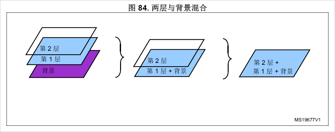
The blending order is fixed, that is, from bottom to top. If two layers are enabled, first layer 1 will be blended with the background color, and then layer 2 will be blended again with the blended color of layer 1 and the background.
See the picture below.
So layer 1 (layer 0) is the background layer, and layer 2 (layer 1) is the foreground layer.
#define LCD_BACKGROUND_LAYER 0x0000
#define LCD_FOREGROUND_LAYER 0x0001
When using a 1024x768 resolution LCD, it is best to use only one layer, namely the first layer mentioned above. Otherwise, when two layers are used, only static images can be displayed, and dynamic refresh will flicker.
Because each layer occupies an SDRAM buffer, when the LCD resolution is too large, the amount of data in the buffer (from SDRAM to LCD) that needs to be refreshed will be larger. When using 2 layers, the amount of data refreshed doubles.
LTDC will always perform a blend between the two layers, even if one of the layers is disabled (even if a layer is disabled using the control register).
3. Layer Window
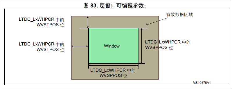
Each layer can be positioned and sized and must be within the active display area.
The window position and size are configured by the upper left and lower right X/Y positions and the internal timing generator containing the sync, back porch size and valid data area. See the LTDC_LxWHPCR and LTDC_WVPCR registers.
Programmable layer position and size define the first/last visible pixel in a line and the first/last visible line in a window. It allows to display a complete image frame or only a part of it.
See Figure 83.
· The first and last visible pixel in a layer are set by configuring WHSTPOS[11:0] and WHSPPOS[11:0] in the LTDC_LxWHPCR register.
· The first and last visible rows in a layer are set by configuring WHSTPOS[11:0] and WHSPPOS[11:0] in the LTDC_LxWVPCR register.
Related configuration register LTDC_LxWHPCR
LTDC Layerx Window Horizontal Position Configuration Register
LTDC layer x window horizontal position configuration register (LTDC_LxWHPCR) (where x = 1..2)
This register defines the horizontal position (first and last pixel) of the layer 1 or layer 2 window.
The first visible pixel of a row is the value programmed in the LTDC_BPCR register at AHBP[10:0] bits + 1.
The last visible pixel of a line is the value of AAW[10:0] bits programmed in the LTDC_AWCR register. All values in this range are allowed.
For example, in the LCD synchronization timing configuration above, set AHBP[10:0] bits to 6 (HSW + HBP- 1: 6 + 1 - 1), then
Here the value of the first visible pixel in a row of the LTDC_LxWHPCR register is 6 + 1 = 7.
The same applies to others.
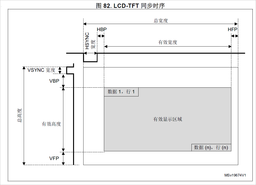
Quoting Figure 82 again:
The window should be defined within the valid display area in the above figure.
It can be clearly seen from the figure above that the first valid display pixel coordinate of a line is HSYNC (HSW) + HBP. The following code describes the relationship between them:
/*For the code, see the LCD sample code under STM32F429I-Discovery in the STM32CubeMX code repository*/
/* Windowing configuration */
/* In this case all the active display area is used to display a picture then :
Horizontal start = horizontal synchronization + Horizontal back porch = 30
Horizontal stop = Horizontal start + window width -1 = 30 + 240 -1
Vertical start = vertical synchronization + vertical back porch = 4
Vertical stop = Vertical start + window height -1 = 4 + 320 -1 */
LTDC_Layer_InitStruct.LTDC_HorizontalStart=HBP+HSW;
LTDC_Layer_InitStruct.LTDC_HorizontalStop =HSW+HBP+LCD_PIXEL_WIDTH-1;
LTDC_Layer_InitStruct.LTDC_VerticalStart =VBP+VSW;
LTDC_Layer_InitStruct.LTDC_VerticalStop =VSW+VBP+LCD_PIXEL_HEIGHT-1;
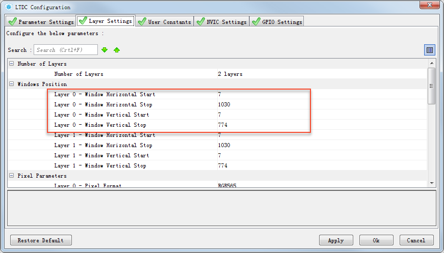
Related configuration in STM32CubeMX:
The generated code is as follows:
pLayerCfg.WindowX0=7;
pLayerCfg.WindowX1=1030;
pLayerCfg.WindowY0=7;
pLayerCfg.WindowY1=774;
...
if(HAL_LTDC_Init(&hltdc)!=HAL_OK)
{
_Error_Handler(__FILE__,__LINE__);
}
4. Default color
Note the difference between this and the background color in the global configuration.
The background color is the color of the background layer in Figure 8.4 above. The default color here is the color outside the layer window - the color of the area outside when the layer window area is smaller than the display window.
Each layer can have a default color in ARGB format, which is used outside the defined layer window or when the layer is disabled.
The default color is configured via the LTDC_LxDCCR register.
The blending operation between the two layers is always performed, even if one of the layers is disabled. To avoid showing the default color when a layer is disabled, set the blending coefficient for this layer in the LTDC_LxBFCR register to its reset value.
This is for layers, because only layers have the concept of windows.
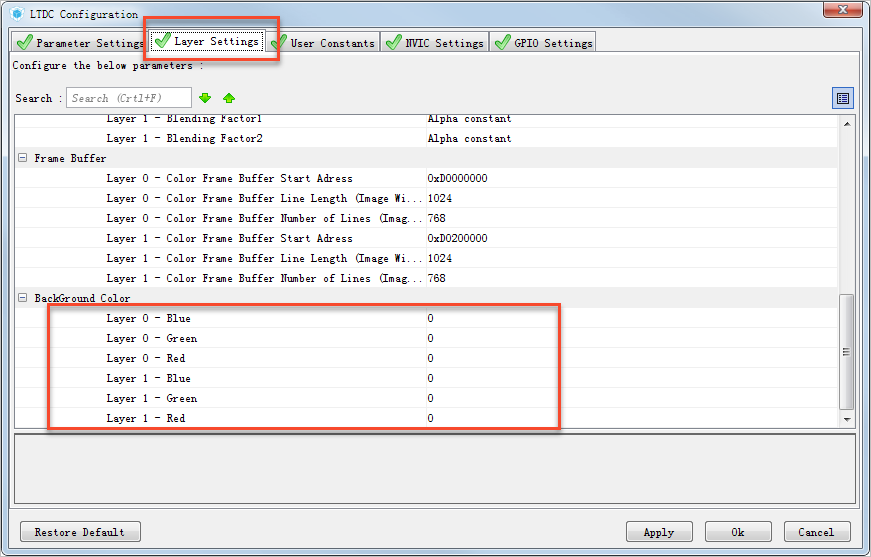
The corresponding code generated by STM32CubeMX is as follows:
// Layer configuration
pLayerCfg.Backcolor.Blue=0;
pLayerCfg.Backcolor.Green=0;
pLayerCfg.Backcolor.Red=0;
if(HAL_LTDC_ConfigLayer(&hltdc,&pLayerCfg,0)!=HAL_OK)
{
Error_Handler(__FILE__,__LINE__);
}
Layer Disable and Default Colors
If two layers are enabled at the same time, layer 0 and layer 1, then layer 1 is disabled:
__HAL_LTDC_LAYER_DISABLE(&hltdc, 1);
__HAL_LTDC_RELOAD_IMMEDIATE_CONFIG(&hltdc);
After layer 1 is disabled, the color of this layer will still participate in the mixing, but the color used in the mixing is the layer default color value (see the layer default color description).
1. After disabling layer 1, this layer will still participate in color mixing.
2. After disabling layer 1, the layer uses the default color to participate in color mixing.
3. To avoid displaying the default color when the layer is disabled, set the blending coefficient of this layer in the LTDC_LxBFCR register to its reset value. Since layer 1 is the foreground layer,
Only then will layer 0 be displayed (unless you set layer 1's alpha value to 0).
When the LCD layer is initialized, layer 1 is not initialized, and only layer 0 is used at this time. This is because the setting value of the layer 1 related register is its reset value at this time.
As mentioned in 3 above, the default color will be disabled at this time.
5. Color frame buffer length and color frame buffer spacing
Color Frame Buffer Length
Every layer has a total line length setting for the color frame buffer in bytes and a number of
lines in the frame buffer configurable in the LTDC_LxCFBLR and LTDC_LxCFBLNR
register respectively.
The line length and the number of lines settings are used to stop the prefetching of data to
the layer FIFO at the end of the frame buffer.
• If it is set to less bytes than required, a FIFO underrun interrupt is generated if it has
been previously enabled.
• If it is set to more bytes than actually required, the useless data read from the FIFO is
discarded. The useless data is not displayed.
Each layer sets the total line length (in bytes) and number of lines in the color frame buffer, which can be configured through the LTDC_LxCFBLR and LTDC_LxCFBLNR registers respectively.
The line length and number of lines are set to prevent data from being prefetched into the layer FIFO at the end of the frame buffer.
· If set below the required bytes, a FIFO underflow interrupt is generated (if previously enabled).
· If set higher than the actual required bytes, useless data read from the FIFO will be discarded. The useless data will not be displayed.
Color Frame Buffer Pitch
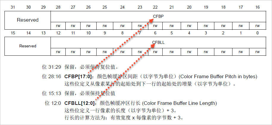
Every layer has a configurable pitch for the color frame buffer, which is the distance between
the start of one line and the beginning of the next line in bytes. It is configured through the
LTDC_LxCFBLR register.
The color framebuffer for each layer has a configurable pitch, which is the distance in bytes between the start of one line and the start of the next.
It is configured through the LTDC_LxCFBLR register.
LTDC_LxCFBLR (LTDC Layerx Color Frame Buffer Length Register) Register
LTDC Layer x color frame buffer length register
Example:
· A frame buffer with a width of 256 pixels (total bytes per row) in RGB565 (2 bytes per pixel) format
256x2=512) requires writing the value 0x02000203 to this register (where spacing = line length).
· A frame buffer with a width of 320 pixels (total bytes per row) in RGB888 (3 bytes per pixel) format
320x3=960) requires writing the value 0x03C003C3 to this register (where spacing = line length).
LTDC_LxCFBLNR (LTDC Layerx ColorFrame Buffer Line Number Register) Register
LTDC Layer x Color Frame Buffer Line Number Register (LTDC_LxCFBLNR) (where x = 1..2)
This register defines the number of lines in the color frame buffer.
Bit 10:0 CFBLNBR[10:0]: Frame Buffer Line Number
These bits define the number of lines in the frame buffer that correspond to the active high width.
NOTE: The number of lines and line length settings define the amount of data that is taken from each frame for each layer. If configured to less than the required bytes, this will result in
Generates a FIFO underflow interrupt (if enabled).
On the other hand, the start address and spacing settings define the correct starting position of each row in the memory.
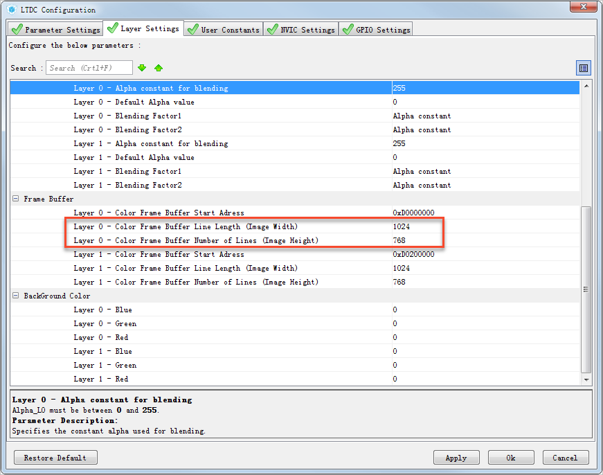
Related configuration in STM32CubeMX:
The corresponding code generated by STM32CubeMX is as follows:
// Layer configuration
pLayerCfg.ImageWidth=1024;
pLayerCfg.ImageHeight=768;
...
if(HAL_LTDC_ConfigLayer(&hltdc,&pLayerCfg,0)!=HAL_OK)
{
_Error_Handler(__FILE__,__LINE__);
}
//HAL_LTDC_ConfigLayer-->LTDC_SetConfig function code:
if(HAL_LTDC_ConfigLayer(&hltdc,&pLayerCfg,0)!=HAL_OK)
{
Error_Handler(__FILE__,__LINE__);
}
/* Configure the color frame buffer pitch in byte */
LTDC_LAYER(hltdc,LayerIdx)->CFBLR &=~(LTDC_LxCFBLR_CFBLL|LTDC_LxCFBLR_CFBP);
LTDC_LAYER(hltdc,LayerIdx)->CFBLR =(((pLayerCfg->ImageWidth*tmp)<<16U)|(((pLayerCfg->WindowX1-pLayerCfg->WindowX0)*tmp) +3U));
/* Configure the frame buffer line number */
LTDC_LAYER(hltdc,LayerIdx)->CFBLNR &=~(LTDC_LxCFBLNR_CFBLNBR);
LTDC_LAYER(hltdc,LayerIdx)->CFBLNR =(pLayerCfg->ImageHeight);
/* Enable LTDC_Layer by setting LEN bit */
LTDC_LAYER(hltdc,LayerIdx)->CR|=(uint32_t)LTDC_LxCR_LEN;
6. Layer blending parameter Alpha
Alpha is actually a coefficient between 0 and 1, which represents transparency as a percentage, with 0 representing complete transparency and 1 representing complete opacity. In addition, alpha blending has different algorithms based on the value of alpha.
The general mixing formula used in the STM32F29 LTDC is:
BC = BF1 x C + BF2 x Cs
BC = mixed color
BF1 = Blending factor 1
C = current layer color
BF2 = Blending Factor 2
Cs = the color of the base layer after blending
The Cs above is the color after the bottom layer is mixed. Since the layer mixing in STM32F29 LTDC is carried out step by step, that is, the 0th layer is mixed with the background layer first, and then the 1st layer and the above mixed color are mixed again, so this is the color after the bottom layer is mixed.
BF1 and BF2 are configured through the register LTDC_LxBFCR, and combined with the LTDC_LxCACR register to complete the calculation and output of the mixed color.
LTDC_LxCACR Constant Alpha Configuration Register
LTDC Layerx Constant Alpha Configuration Register
This register defines the constant alpha value used in alpha blending (divided by 255 by hardware).
Bit 7:0 CONSTA[7:0]: Constant Alpha
These bits configure the constant alpha used when blending. Constant alpha is divided by 255 by hardware.
Example: If the programmed constant alpha is 0xFF, the constant alpha value is 255/255=1
LTDC Layer x Mixing Coefficient Configuration Register (LTDC_LxBFCR) (where x=1..2)
LTDC Layerx Blending Factors Configuration Register
Reset value: 0x0000 0607
Bit 10:8 BF1[2:0]: Blending Factor 1
These bits select the mixing factor F1, whose values and their meanings are as follows:
100: Constant Alpha
110: Pixel Alpha x Constant Alpha
Bit 2:0 BF2[2:0]: Blending Factor 2
These bits select the mixing factor F2, whose values and their meanings are as follows:
101:1 - Constant Alpha
That is, 1 minus Constant Alpha
111:1 - (Pixel Alpha x Constant Alpha)
That is, 1 minus (Pixel Alpha x Constant Alpha)
The constant Alpha above is the value configured in the LTDC_LxCACR register.
Pixel Alpha is the Alpha value contained in the pixel value. For example, in the ARGB8888 format, a pixel is 32 bits, 4 bytes, and the highest byte is the Alpha value. The Alpha value in all the calculations above is
Both represent (integer value in configuration/255).
For example, when BF1 is 110, the mixing coefficient F1 is:
(Alpha integer value in pixel / 255) x (LTDC_LxCACR constant alpha configuration value / 255)
When BF2 is 111, the mixing coefficient F2 is:
1 - (alpha integer value in pixel / 255) x (LTDC_LxCACR constant alpha configuration value / 255)
Example: Enable only layer 1, BF1 configured as constant alpha
BF2 is configured as 1-constant alpha
Constant Alpha: The constant alpha programmed in the LxCACR register is 240 (0xF0). Therefore, the constant alpha value is
240/255 = 0.94
C: The current layer color is 128
Cs: background color is 48
Layer 1 is blended with the background color.
BC = ConstantAlpha x C + (1 - ConstantAlpha) x Cs = 0.94 x 128 + (1- 0.94) x 48 = 123.
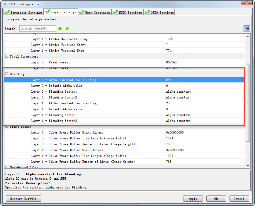
Related configuration in STM32CubeMX:
The corresponding code generated by STM32CubeMX is as follows:
pLayerCfg.Alpha=255;
pLayerCfg.Alpha0=0;
pLayerCfg.BlendingFactor1=LTDC_BLENDING_FACTOR1_CA;
pLayerCfg.BlendingFactor2=LTDC_BLENDING_FACTOR2_CA;
//HAL_LTDC_ConfigLayer-->LTDC_SetConfig
/* Configure the default color values */
tmp=((uint32_t)(pLayerCfg->Backcolor.Green)<<8U);
tmp1=((uint32_t)(pLayerCfg->Backcolor.Red)<<16U);
tmp2=(pLayerCfg->Alpha0<<24U);
LTDC_LAYER(hltdc,LayerIdx)->DCCR&=~(LTDC_LxDCCR_DCBLUE|LTDC_LxDCCR_DCGREEN|LTDC_LxDCCR_DCRED|LTDC_LxDCCR_DCALPHA);
LTDC_LAYER(hltdc,LayerIdx)->DCCR=(pLayerCfg->Backcolor.Blue|tmp|tmp1|tmp2);
/* Specifies the constant alpha value */
LTDC_LAYER(hltdc,LayerIdx)->CACR&=~(LTDC_LxCACR_CONSTA);
LTDC_LAYER(hltdc,LayerIdx)->CACR=(pLayerCfg->Alpha);
/* Specifies the blending factors */
LTDC_LAYER(hltdc,LayerIdx)->BFCR&=~(LTDC_LxBFCR_BF2|LTDC_LxBFCR_BF1);
LTDC_LAYER(hltdc,LayerIdx)->BFCR=(pLayerCfg->BlendingFactor1|pLayerCfg->BlendingFactor2);
Default Alpha value
The default alpha value is for the layer's default color, which is used outside of the defined layer window or when the layer is disabled.
See Section 4 above for more information on default colors.
When outside the window and the layer is disabled, the alpha parameter value is used for color mixing, that is, the mixing parameter of the default color RGB and the underlying color.
At this time, the general mixing formula above should also be followed BC = BF1 x C + BF2 x Cs, except that the parameters in BF1 and BF2 are
The constant Alpha is replaced by this Default Alpha value (the STM32F429 documentation does not explain this).
In the description of the default colors in Section 4 above, there are:
To avoid showing the default color when a layer is disabled, set the blending coefficient for this layer in the LTDC_LxBFCR register to its reset value.
The reset value of LTDC_LxBFCR is 0x0000 0607 (see above), that is, BF1 is 110 and BF2 is 111.
The mixing coefficient F1 is:
BF1 (alpha integer value in pixel / 255) x (LTDC_LxCACR constant alpha configuration value / 255)
The mixing coefficient F2 is:
1 - (alpha integer value in pixel / 255) x (LTDC_LxCACR constant alpha configuration value / 255)
The alpha integer value in the pixel should be 0 at this time, so both F1 and F2 are 0.
Then the mixed formula BC = BF1 x C + BF2 x Cs
BC = 0.
test
//The global background color of the LCD is configured to 0, which is black
// Below is the configuration of layer 0, and only this layer is used.
pLayerCfg.WindowX0=7;
pLayerCfg.WindowX1=1030;
pLayerCfg.WindowY0=7;
pLayerCfg.WindowY1=774-100; //Layer window is smaller than the effective display area
pLayerCfg.PixelFormat=LTDC_PIXEL_FORMAT_RGB565;
pLayerCfg.Alpha=255;
pLayerCfg.Alpha0=255; //Alpha value in the default color. Modifying this value will change the color of the area outside the layer window (change in transparency)
pLayerCfg.BlendingFactor1=LTDC_BLENDING_FACTOR1_PAxCA; //Note that the pixel must be set to participate in F1 calculation at this time, and the pixel alpha value at this time is the corresponding value in the layer default color
pLayerCfg.BlendingFactor2=LTDC_BLENDING_FACTOR2_PAxCA; //Note that the pixel must be set to participate in F1 calculation at this time, and the pixel alpha value at this time is the corresponding value in the layer default color
pLayerCfg.FBStartAdress=0xD0000000;
pLayerCfg.ImageWidth=1024;
pLayerCfg.ImageHeight=768-100; //Layer window, smaller than the effective display area
pLayerCfg.Backcolor.Blue=0;
pLayerCfg.Backcolor.Green=0xff;
pLayerCfg.Backcolor.Red=0;
Previous article:DMA2D acceleration of LTDC in STM32F429
Next article:Use of RGB screen based on STM32F429
- Popular Resources
- Popular amplifiers
 Professor at Beihang University, dedicated to promoting microcontrollers and embedded systems for over 20 years.
- LED chemical incompatibility test to see which chemicals LEDs can be used with
- Application of ARM9 hardware coprocessor on WinCE embedded motherboard
- What are the key points for selecting rotor flowmeter?
- LM317 high power charger circuit
- A brief analysis of Embest's application and development of embedded medical devices
- Single-phase RC protection circuit
- stm32 PVD programmable voltage monitor
- Introduction and measurement of edge trigger and level trigger of 51 single chip microcomputer
- Improved design of Linux system software shell protection technology
- What to do if the ABB robot protection device stops
- Huawei's Strategic Department Director Gai Gang: The cumulative installed base of open source Euler operating system exceeds 10 million sets
- Download from the Internet--ARM Getting Started Notes
- Learn ARM development(22)
- Learn ARM development(21)
- Learn ARM development(20)
- Learn ARM development(19)
- Learn ARM development(14)
- Learn ARM development(15)
- Analysis of the application of several common contact parts in high-voltage connectors of new energy vehicles
- Wiring harness durability test and contact voltage drop test method
- Friends who are familiar with the MSP430 series of microcontrollers, please take a look (Beijing)
- How many of you guys are engaged in the FPGA industry?
- Implementation of Embedded RTOS on MSP430 MCU
- ADC parameter group delay time
- 【Beetle ESP32-C3】IX. OLED clock and weather assistant logic description (Arduino)
- 【ST NUCLEO-H743ZI Review】USB MSC Function Test
- WiFi indoor positioning technology and its evolution that has triggered the Internet of Things application
- Help: Does anyone have a power supply design that complies with industry design standards IEC61010, IEC60950?
- [Silicon Labs BG22-EK4108A Bluetooth Development Evaluation] + Development Board Firmware Upgrade
- Assembly Language (4th Edition)

 DS1667N-50


 京公网安备 11010802033920号