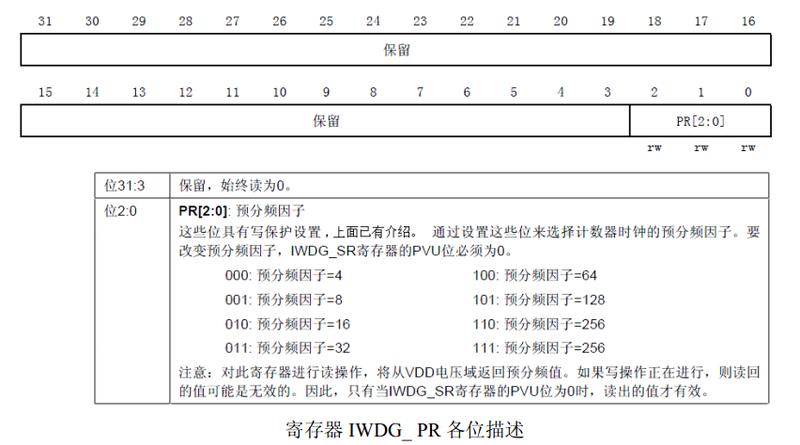
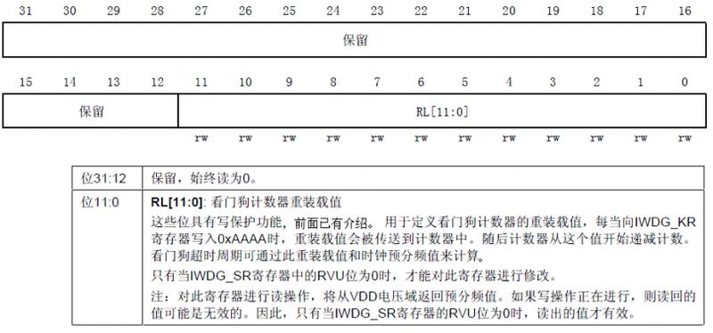
The independent watchdog of STM32 is driven by a dedicated internal 40Khz low-speed clock, that is, it is still effective even if the main clock fails. Here we need to note that the clock of the independent watchdog is not an accurate 40Khz, but a clock that varies between 30 and 60Khz. It is just that we estimate it to be 40Khz. The watchdog is not very demanding on time, and a little deviation in the clock is acceptable.
Several registers related to independent watchdog
Working principle of independent watchdog: Write 0XCCCC in the key value register (IWDG_KR) to enable the independent watchdog. At this time, the counter starts to count down from its reset value OXFFF. When the counter counts to the end 0X000, a reset signal (IWDG_RESET) is generated. Whenever 0XAAAA is written to the register IWDG_KR, the value in IWDG_RLR will be reloaded into the counter to avoid a watchdog reset.
Write protection of prescaler register (IWDG_PR) and reload register (IWDG_RLR): IWDG_PR and IWDG_RLR registers have write protection function. To modify the value of these two registers, first write 0X5555 to IWDG_KR. Writing to this register with a different value or reloading (writing 0XAAAA) will restart the write protection.


2. Independent watchdog startup process

2. Independent watchdog startup process
In this way, as long as we set the above three registers accordingly, we can start the STM32 independent watchdog. The startup process is as follows:
2.1. 1. Inhale 0X5555 into IWDG_KR
Through this step we have cancelled the write protection of IWDG_PR and IWDG_RLR. The next step is to set their initial values.
Set the initial values of IWDG_PR and IWDG_RLR.
Let's calculate the watchdog feeding time (watchdog overflow time) calculation formula
All=((4*2^prer)*rlr)/40
Tout is the watchdog overflow time (in ms), prer is the watchdog clock pre-division value (IWDG_PR value), ranging from 0 to 7, and rlr is the watchdog reload value (IWDG_RLR). For example, if we set prer to 4 and rlr to 625, we can calculate Tout = 64 * 625 / 40 = 1000ms, so the watchdog overflow time is 1S. As long as 0XAAAA is sucked into IWDG_KR once within this second, the watchdog will not be reset (it is also possible to write multiple times) (since the watchdog clock is not accurate to 40Khz, do not feed the dog too late to avoid a watchdog reset).
2.2. 2. Write 0XAAAA to IWDG_KR
This sentence can load the initial count value in the reload register (IWDG_RLR) into the watchdog counter (you can also use this command to feed the watchdog).
2.3. 3. Write 0XCCCC to IWDG_KR
Through this sentence, we have started the watchdog of STM32. After enabling the watchdog, we must feed the dog at a certain interval in the program, otherwise it will cause the program to reset. Taking advantage of this, we use an LED to indicate whether it is reset and verify the independent watchdog.
The watchdog core in STM32 is inside the chip and does not require an external circuit. Here we use two IO ports in the external circuit, one for inputting the dog feeding signal and the other for indicating whether the program is reset. The WK_UP button is used to feed the dog and DS0 is used to indicate program restart.
Previous article:The difference between stm32 independent watchdog and window watchdog
Next article:STM32 self-study notes - watchdog
Recommended ReadingLatest update time:2024-11-23 03:06


- Popular Resources
- Popular amplifiers
- Naxin Micro and Xinxian jointly launched the NS800RT series of real-time control MCUs
- How to learn embedded systems based on ARM platform
- Summary of jffs2_scan_eraseblock issues
- Application of SPCOMM Control in Serial Communication of Delphi7.0
- Using TComm component to realize serial communication in Delphi environment
- Bar chart code for embedded development practices
- Embedded Development Learning (10)
- Embedded Development Learning (8)
- Embedded Development Learning (6)
 Professor at Beihang University, dedicated to promoting microcontrollers and embedded systems for over 20 years.
- Intel promotes AI with multi-dimensional efforts in technology, application, and ecology
- ChinaJoy Qualcomm Snapdragon Theme Pavilion takes you to experience the new changes in digital entertainment in the 5G era
- Infineon's latest generation IGBT technology platform enables precise control of speed and position
- Two test methods for LED lighting life
- Don't Let Lightning Induced Surges Scare You
- Application of brushless motor controller ML4425/4426
- Easy identification of LED power supply quality
- World's first integrated photovoltaic solar system completed in Israel
- Sliding window mean filter for avr microcontroller AD conversion
- What does call mean in the detailed explanation of ABB robot programming instructions?
- STMicroelectronics discloses its 2027-2028 financial model and path to achieve its 2030 goals
- 2024 China Automotive Charging and Battery Swapping Ecosystem Conference held in Taiyuan
- State-owned enterprises team up to invest in solid-state battery giant
- The evolution of electronic and electrical architecture is accelerating
- The first! National Automotive Chip Quality Inspection Center established
- BYD releases self-developed automotive chip using 4nm process, with a running score of up to 1.15 million
- GEODNET launches GEO-PULSE, a car GPS navigation device
- Should Chinese car companies develop their own high-computing chips?
- Infineon and Siemens combine embedded automotive software platform with microcontrollers to provide the necessary functions for next-generation SDVs
- Continental launches invisible biometric sensor display to monitor passengers' vital signs
- Playing with Zynq Serial 44——[ex63] Image smoothing processing of MT9V034 camera
- [2022 Digi-Key Innovation Design Competition] Material Unboxing STM32H745I-DISCO
- Supplementary chapter of motor PID control - Introduction to the serial port protocol of the Wildfire host computer
- 485 interface EMC circuit design scheme!
- Help! CCS7.3 enters the exit.c file after entering debug mode. I don't know how to solve it
- Share Gigabit Ethernet port circuit design
- [RVB2601 creative application development] 2. CH2601 serial port receiving
- How to draw this shape in Protel 99se
- Fairchild Semiconductor adds analog product development team to develop power analog business
- A summary of the most downloaded electronic technical materials this week (2020.5.1~9), each one is a classic


 usb_host_device_code
 Transplantation of real-time operating system RT-ThreadSmart on STM32MP1


 京公网安备 11010802033920号