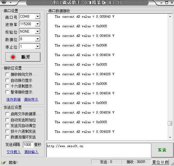
Mainly the writing of adc.h and adc.c files (written as add.h and add.c during the experiment)
After debugging for a whole morning, I found that the clock was set wrongly. RCC_APB2PeriphClockCmd(RCC_APB2Periph_GPIOC|RCC_APB2Periph_ADC1,ENABLE);
It is set to APB1, so only 0v can appear. Beware! ! !
The add.h code is as follows:
#ifndef _ADD_H
#define _ADD_H
#include "stm32f10x.h"
void ADC_Configure();
#endif
The add.c code is as follows:
#include "add.h"
#define ADC1_DR_Address ((u32)0x40012400 + 0x4C)
__IO uint16_t ADC_ConvertedValue;
static void ADC_GPIO_Config()
{
GPIO_InitTypeDef GPIO_InitStructure;
RCC_AHBPeriphClockCmd(RCC_AHBPeriph_DMA1 ,ENABLE);
RCC_APB2PeriphClockCmd(RCC_APB2Periph_GPIOC|RCC_APB2Periph_ADC1,ENABLE);
GPIO_InitStructure.GPIO_Mode = GPIO_Mode_AIN;
GPIO_InitStructure.GPIO_Pin = GPIO_Pin_1;
GPIO_Init(GPIOC,&GPIO_InitStructure);
}
static void ADC_DMA_Config()
{
ADC_InitTypeDef ADC_InitStructure;
DMA_InitTypeDef DMA_InitStructure;
DMA_DeInit(DMA1_Channel1);
DMA_InitStructure.DMA_BufferSize = 1;
DMA_InitStructure.DMA_DIR = DMA_DIR_PeripheralSRC;
DMA_InitStructure.DMA_M2M = DMA_M2M_Disable;
DMA_InitStructure.DMA_MemoryBaseAddr = (u32)&ADC_ConvertedValue;
DMA_InitStructure.DMA_MemoryDataSize = DMA_MemoryDataSize_HalfWord;
DMA_InitStructure.DMA_MemoryInc = DMA_MemoryInc_Disable;
DMA_InitStructure.DMA_Mode = DMA_Mode_Circular;
DMA_InitStructure.DMA_PeripheralBaseAddr = ADC1_DR_Address;
DMA_InitStructure.DMA_PeripheralDataSize = DMA_PeripheralDataSize_HalfWord;
DMA_InitStructure.DMA_PeripheralInc = DMA_PeripheralInc_Disable;
DMA_InitStructure.DMA_Priority = DMA_Priority_High;
DMA_Init(DMA1_Channel1,&DMA_InitStructure);
DMA_Cmd(DMA1_Channel1, ENABLE);
ADC_InitStructure.ADC_ContinuousConvMode = ENABLE;
ADC_InitStructure.ADC_DataAlign = ADC_DataAlign_Right;
ADC_InitStructure.ADC_ExternalTrigConv = ADC_ExternalTrigConv_None;
ADC_InitStructure.ADC_Mode = ADC_Mode_Independent;
ADC_InitStructure.ADC_NbrOfChannel = 1;
ADC_InitStructure.ADC_ScanConvMode = DISABLE;
ADC_Init(ADC1,&ADC_InitStructure);
RCC_ADCCLKConfig(RCC_PCLK2_Div8);
ADC_RegularChannelConfig(ADC1,ADC_Channel_11,1,ADC_SampleTime_55Cycles5);
ADC_DMACmd(ADC1,ENABLE);
ADC_Cmd(ADC1,ENABLE);
ADC_ResetCalibration(ADC1);
while(ADC_GetResetCalibrationStatus(ADC1));
ADC_StartCalibration(ADC1);
while(ADC_GetCalibrationStatus(ADC1));
ADC_SoftwareStartConvCmd(ADC1,ENABLE);
}
void ADC_Configure()
{
ADC_GPIO_Config();
ADC_DMA_Config();
}
The usart.h code is as follows:
#ifndef _USART_H
#define _USAET_H
#include
void Usart_GPIO_Config(void);
int fputc(int ch,FILE *f);
#endif
The usart.c code is as follows:
#include "usart.h"
#include "stm32f10x.h"
void Usart_GPIO_Config()
{
USART_InitTypeDef USART_InitStructure;
GPIO_InitTypeDef GPIO_InitStructure;
RCC_APB2PeriphClockCmd(RCC_APB2Periph_GPIOA|RCC_APB2Periph_USART1,ENABLE);
GPIO_InitStructure.GPIO_Mode = GPIO_Mode_AF_PP;
GPIO_InitStructure.GPIO_Pin = GPIO_Pin_9;
GPIO_InitStructure.GPIO_Speed = GPIO_Speed_50MHz;
GPIO_Init(GPIOA,&GPIO_InitStructure);
GPIO_InitStructure.GPIO_Mode = GPIO_Mode_IN_FLOATING;
GPIO_InitStructure.GPIO_Pin = GPIO_Pin_10;
GPIO_Init(GPIOA,&GPIO_InitStructure); //Note that this must be added for unclear reasons
USART_InitStructure.USART_BaudRate = 115200;
USART_InitStructure.USART_HardwareFlowControl = USART_HardwareFlowControl_None;
USART_InitStructure.USART_Mode = USART_Mode_Tx|USART_Mode_Rx;
USART_InitStructure.USART_Parity = USART_Parity_No;
USART_InitStructure.USART_StopBits = USART_StopBits_1;
USART_InitStructure.USART_WordLength = USART_WordLength_8b;
USART_Init(USART1,&USART_InitStructure);
USART_Cmd(USART1,ENABLE);
}
int fputc(int ch,FILE *f)
{
USART_SendData(USART1,(unsigned char)ch);
while(!(USART1->SR & USART_FLAG_TXE));
return ch;
}
The main.c code is as follows:
/******************** (C) COPYRIGHT 2013 ******************************
* File name: main.c
* Description: Project template built with version 3.5.0.
* Experimental platform: WildFire STM32 development board
* Library version: ST3.5.0
*
* Version: v1.0
**********************************************************************************/
#include "stm32f10x.h"
#include "add.h"
#include "usart.h"
void delay(__IO uint32_t count);
extern __IO uint16_t ADC_ConvertedValue;
float ADC_ConvertedValueLocal;
/*
* Function name: main
* Description: Main function
* Input: None
* Output: None
*/
int main(void)
{
Usart_GPIO_Config();
ADC_Configure();
while(1)
{
ADC_ConvertedValueLocal =(float) ADC_ConvertedValue/4096*3.3; // Read the converted AD value
printf("\r\n The current AD value = 0x%04X \r\n", ADC_ConvertedValue);
printf("\r\n The current AD value = %f V \r\n",ADC_ConvertedValueLocal);
delay(0x01fffff0);
}
// add your code here ^_^。
}
/******************* (C) COPYRIGHT 2013 *****END OF FILE************/
void delay(__IO uint32_t count)
{
for(;count>0;count--);
}

Previous article:stm32 learning ten
Next article:STM32 learning six
Recommended ReadingLatest update time:2024-11-15 23:56


- Popular Resources
- Popular amplifiers
 Professor at Beihang University, dedicated to promoting microcontrollers and embedded systems for over 20 years.
- LED chemical incompatibility test to see which chemicals LEDs can be used with
- Application of ARM9 hardware coprocessor on WinCE embedded motherboard
- What are the key points for selecting rotor flowmeter?
- LM317 high power charger circuit
- A brief analysis of Embest's application and development of embedded medical devices
- Single-phase RC protection circuit
- stm32 PVD programmable voltage monitor
- Introduction and measurement of edge trigger and level trigger of 51 single chip microcomputer
- Improved design of Linux system software shell protection technology
- What to do if the ABB robot protection device stops
- Allegro MicroSystems Introduces Advanced Magnetic and Inductive Position Sensing Solutions at Electronica 2024
- Car key in the left hand, liveness detection radar in the right hand, UWB is imperative for cars!
- After a decade of rapid development, domestic CIS has entered the market
- Aegis Dagger Battery + Thor EM-i Super Hybrid, Geely New Energy has thrown out two "king bombs"
- A brief discussion on functional safety - fault, error, and failure
- In the smart car 2.0 cycle, these core industry chains are facing major opportunities!
- The United States and Japan are developing new batteries. CATL faces challenges? How should China's new energy battery industry respond?
- Murata launches high-precision 6-axis inertial sensor for automobiles
- Ford patents pre-charge alarm to help save costs and respond to emergencies
- New real-time microcontroller system from Texas Instruments enables smarter processing in automotive and industrial applications

 usb_host_device_code
 Transplantation of real-time operating system RT-ThreadSmart on STM32MP1


 京公网安备 11010802033920号