China Mobile Multimedia Broadcasting (CMMB) is a mobile multimedia broadcasting standard independently developed by China with completely independent intellectual property rights. At present, the CMMB network in major cities across the country is being built and improved, and the coverage test of CMMB signals provides important data basis for network optimization and adjustment. The construction of digital TV broadcasting network is a long and complex process, which requires continuous adjustment and optimization to achieve an ideal effect. Only effective and accurate network coverage test can provide a reliable basis for adjustment and optimization. A mature and stable CMMB network coverage test system is of great significance to the development of CMMB. Therefore, it is necessary to design a coverage test system for CMMB network.
This design realizes real-time monitoring of CMMB network coverage of test points based on high-performance single-chip microcomputer STM32 and GPRS wireless communication solution, and uses GPS receiver to upload the geographical location information of the test terminal to the server, completing the precise positioning of the monitoring terminal. The
terminal board adopts solar power supply system to ensure its long-term stable operation without power supply and personnel guarding. Finally, through comprehensive testing, all required functions can be realized, which fully meets the requirements of this design.
1 Test requirements analysis
In order to monitor the test points in real time and accurately, the following points need to be done. The geographical location of the test site, including longitude and latitude, is counted at least once a second; the battery power of the terminal board is updated in real time; the average power within the 8 M signal bandwidth, in dBm, is counted once a second, and the measurement accuracy reaches ±1 dBm; the LDPC packet error rate and RS packet error rate of CMMB signal decoding are counted once a second; the server side can change the information reporting time interval at any time, and can change the terminal tuner and demodulator configuration parameters to adapt to the different demodulation parameters in different regions.
2 Overall design
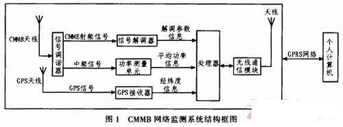
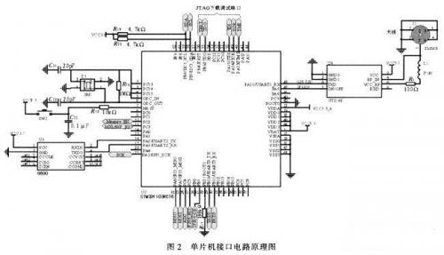
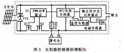
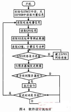
This system is divided into a test terminal and a server side. The server side only needs a personal computer with good performance, and the test terminal is mainly composed of the following modules: RF front-end module module, power measurement and storage module, GPS receiver, solar power supply module, processor module and GPRS wireless communication module. Each module is mainly connected and communicated through the GPIO port of the STM32 microprocessor. The processor needs to tune the channel and set the demodulation parameters for the tuner and demodulator of the RF front end, and read information such as RS packet error rate and LDPC packet error rate. The CMMB signal tuner mainly tunes the high-frequency signal received from the antenna to output the intermediate frequency signal; the CMMB tuning and demodulation module mainly demodulates the signal and decodes the channel; the power measurement and storage module is responsible for converting the signal power into a level signal and sending it to the ADC of STM32 and storing the system setting parameters. The GPS receiver is used to obtain the geographical location information of the monitoring point. Finally, the processor sends the information to the server through the GPRS wireless module and receives the control command from the server. The overall structure of the system is shown in Figure 1. CMMB network monitoring system structure diagram 3 System hardware design 3.1 RF front-end module The RF front-end module includes a tuning unit and a demodulation unit. The RF signal tuning module in this system uses MXL5007. The chip can receive continuous frequency band signals from 44 to 885 MHz through antenna or wire, and tune the input RF signal to output 4 to 44 MHz intermediate frequency signal. This chip also has the function of looping out the original RF signal without loss, which allows the chip to output the intermediate frequency signal to the power measurement module while also looping out a CMMB signal to the post-stage demodulation module without loss, which is an ideal choice for the tuner of this system. The tuning and demodulation module uses the IF206 chip of Innovision, which supports the CMMB broadcast channel standard and multiplexing standard; can receive satellite signals and terrestrial signals at the same time; low power consumption, low cost, and no special requirements for front-end and back-end equipment. 3.2 GPRS wireless communication module This system uses the GPRS wireless communication solution, using the Fibocom G600 module, supporting Dual 900/1800 or 850/1900 dual-frequency. The G600 module has a small appearance, low power consumption, reliable GPRS data connection, built-in TCP/IP protocol stack, and uses serial communication 3.3 GPS receiver The monitoring terminal collects the geographical information of the monitoring point through the GPS receiver, including: longitude and latitude, altitude, etc. The test system displays the test data at the corresponding position of the map according to the obtained GPS information. The GTS-4E-00 module is selected in this system, which is packaged in stamp patch and can adapt to harsh working environments such as high temperature, high humidity, and electromagnetic interference. Its simplified circuit diagram is shown in Figure 2. TXD is connected to STM32 serial port 1, the module wake-up end is connected to PA9, and J1 is the receiving antenna. Schematic diagram of the single-chip interface circuit 3.4 Processor module The processor is the core of the entire monitoring terminal, responsible for collecting data from the RF front end and communicating with the server. The processor uses the STM32F103RCT6 single-chip microcomputer, which is a new 32-bit embedded microprocessor based on the Cortex-M3 core. It combines high performance, real-time, low power consumption, and high integration. The system clock is as high as 72 M, the development is simple, and a variety of peripherals are integrated in the chip. The circuit diagram of the single-chip microcomputer is shown in Figure 2. Among them, the PB6 and PB7 ports of the single-chip microcomputer are its IIC interfaces, responsible for communicating with MXL5007 and the storage chip AT24C1024; the PA5-PA7 ports are its SPI interfaces, used to communicate with IF206; the PA10 port is the serial port 1 receiving end, used to receive GPS module data, and the PA9 port is used to enable the GPS module; PA2 and PA3 are serial port 3, used to communicate with the GPRS module G600; PC2 and PC3 are respectively used as the enable and reset ends of MXL5007; there are two 12-bit ADCs inside the STM32, and PC4 is the internal ADC1 analog input port, which is used to measure the average power of the CMMB signal. 3.5 Solar power supply module The test terminal adopts solar power supply, so that the terminal can work stably for a long time in the absence of power supply and unattended state. The power supply interface of the monitoring terminal board adopts DC-12 V, and adopts solar power supply. The controller is designed to manage the charging and discharging of the battery. This controller is designed for solar DC power supply system, and uses an intelligent controller with a dedicated computer chip. The functional block diagram of the controller is shown in Figure 3. Principle block diagram of solar controller 4 System software design The software programming of the STM32 processor adopts C language programming, and the development environment is MDK-4.0. The basic principle of the software is shown in Figure 4. Basic principle of software After the system is turned on, it is initialized, including the initialization of each peripheral of STM32, reading the parameter values previously set by the system from EEPROM, and initializing MXL5007 and IF206. After the system is initialized, the remaining power information of the solar battery, GPS information, RS packet error rate, LDPC bit error rate, signal average and other information are read respectively, and then it is determined whether to establish a connection with the server. After the connection is successfully established, the data is uploaded to the server at the set time interval; at the same time, the command information from the server is always checked, such as setting the time interval for uploading change information, the threshold values of each parameter, the frequency of the tuning and demodulation chip, etc. After the parameters are modified, they are immediately stored in the EEPROM to prevent the power-off information from being lost. These parameters are read again after the next startup. 5 Equipment prototype and system joint debugging After the test terminal equipment prototype and server software were completed, the project team used the equipment prototype and server software to conduct system joint debugging. The project team selected 3 monitoring points in Beijing. The monitoring point information is shown in Table 1. A CMMB monitoring terminal was placed at each of the 3 monitoring points, as shown in Figure 5. Monitoring point test results

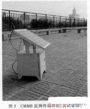
CMMB monitoring terminal prototype
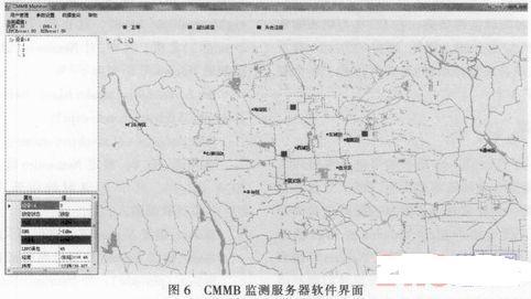
Each monitoring point transmits the monitoring parameters to the server in real time. The server obtains the monitoring data through the IP network and performs analysis and alarm processing according to the software settings. The monitoring interface of the server software is shown in Figure 6. CMMB monitoring server software interface Through equipment joint debugging, the project team optimized the system performance and improved the stability of the system. After several days of experiments, it was proved that the monitoring system can timely and effectively respond to the signal status of the CMMB network. 6 Conclusion The monitoring system uses the processor STM32 development platform and GPRS wireless communication solution to successfully realize the real-time monitoring of the user-side CMMB network coverage, providing a highly efficient and convenient means of supervision for the majority of engineering and technical personnel, and meeting the design requirements.
Keywords:STM32
Reference address:Design and implementation of CMMB intelligent network monitoring system based on STM32
This design realizes real-time monitoring of CMMB network coverage of test points based on high-performance single-chip microcomputer STM32 and GPRS wireless communication solution, and uses GPS receiver to upload the geographical location information of the test terminal to the server, completing the precise positioning of the monitoring terminal. The
terminal board adopts solar power supply system to ensure its long-term stable operation without power supply and personnel guarding. Finally, through comprehensive testing, all required functions can be realized, which fully meets the requirements of this design.
1 Test requirements analysis
In order to monitor the test points in real time and accurately, the following points need to be done. The geographical location of the test site, including longitude and latitude, is counted at least once a second; the battery power of the terminal board is updated in real time; the average power within the 8 M signal bandwidth, in dBm, is counted once a second, and the measurement accuracy reaches ±1 dBm; the LDPC packet error rate and RS packet error rate of CMMB signal decoding are counted once a second; the server side can change the information reporting time interval at any time, and can change the terminal tuner and demodulator configuration parameters to adapt to the different demodulation parameters in different regions.
2 Overall design
This system is divided into a test terminal and a server side. The server side only needs a personal computer with good performance, and the test terminal is mainly composed of the following modules: RF front-end module module, power measurement and storage module, GPS receiver, solar power supply module, processor module and GPRS wireless communication module. Each module is mainly connected and communicated through the GPIO port of the STM32 microprocessor. The processor needs to tune the channel and set the demodulation parameters for the tuner and demodulator of the RF front end, and read information such as RS packet error rate and LDPC packet error rate. The CMMB signal tuner mainly tunes the high-frequency signal received from the antenna to output the intermediate frequency signal; the CMMB tuning and demodulation module mainly demodulates the signal and decodes the channel; the power measurement and storage module is responsible for converting the signal power into a level signal and sending it to the ADC of STM32 and storing the system setting parameters. The GPS receiver is used to obtain the geographical location information of the monitoring point. Finally, the processor sends the information to the server through the GPRS wireless module and receives the control command from the server. The overall structure of the system is shown in Figure 1. CMMB network monitoring system structure diagram 3 System hardware design 3.1 RF front-end module The RF front-end module includes a tuning unit and a demodulation unit. The RF signal tuning module in this system uses MXL5007. The chip can receive continuous frequency band signals from 44 to 885 MHz through antenna or wire, and tune the input RF signal to output 4 to 44 MHz intermediate frequency signal. This chip also has the function of looping out the original RF signal without loss, which allows the chip to output the intermediate frequency signal to the power measurement module while also looping out a CMMB signal to the post-stage demodulation module without loss, which is an ideal choice for the tuner of this system. The tuning and demodulation module uses the IF206 chip of Innovision, which supports the CMMB broadcast channel standard and multiplexing standard; can receive satellite signals and terrestrial signals at the same time; low power consumption, low cost, and no special requirements for front-end and back-end equipment. 3.2 GPRS wireless communication module This system uses the GPRS wireless communication solution, using the Fibocom G600 module, supporting Dual 900/1800 or 850/1900 dual-frequency. The G600 module has a small appearance, low power consumption, reliable GPRS data connection, built-in TCP/IP protocol stack, and uses serial communication 3.3 GPS receiver The monitoring terminal collects the geographical information of the monitoring point through the GPS receiver, including: longitude and latitude, altitude, etc. The test system displays the test data at the corresponding position of the map according to the obtained GPS information. The GTS-4E-00 module is selected in this system, which is packaged in stamp patch and can adapt to harsh working environments such as high temperature, high humidity, and electromagnetic interference. Its simplified circuit diagram is shown in Figure 2. TXD is connected to STM32 serial port 1, the module wake-up end is connected to PA9, and J1 is the receiving antenna. Schematic diagram of the single-chip interface circuit 3.4 Processor module The processor is the core of the entire monitoring terminal, responsible for collecting data from the RF front end and communicating with the server. The processor uses the STM32F103RCT6 single-chip microcomputer, which is a new 32-bit embedded microprocessor based on the Cortex-M3 core. It combines high performance, real-time, low power consumption, and high integration. The system clock is as high as 72 M, the development is simple, and a variety of peripherals are integrated in the chip. The circuit diagram of the single-chip microcomputer is shown in Figure 2. Among them, the PB6 and PB7 ports of the single-chip microcomputer are its IIC interfaces, responsible for communicating with MXL5007 and the storage chip AT24C1024; the PA5-PA7 ports are its SPI interfaces, used to communicate with IF206; the PA10 port is the serial port 1 receiving end, used to receive GPS module data, and the PA9 port is used to enable the GPS module; PA2 and PA3 are serial port 3, used to communicate with the GPRS module G600; PC2 and PC3 are respectively used as the enable and reset ends of MXL5007; there are two 12-bit ADCs inside the STM32, and PC4 is the internal ADC1 analog input port, which is used to measure the average power of the CMMB signal. 3.5 Solar power supply module The test terminal adopts solar power supply, so that the terminal can work stably for a long time in the absence of power supply and unattended state. The power supply interface of the monitoring terminal board adopts DC-12 V, and adopts solar power supply. The controller is designed to manage the charging and discharging of the battery. This controller is designed for solar DC power supply system, and uses an intelligent controller with a dedicated computer chip. The functional block diagram of the controller is shown in Figure 3. Principle block diagram of solar controller 4 System software design The software programming of the STM32 processor adopts C language programming, and the development environment is MDK-4.0. The basic principle of the software is shown in Figure 4. Basic principle of software After the system is turned on, it is initialized, including the initialization of each peripheral of STM32, reading the parameter values previously set by the system from EEPROM, and initializing MXL5007 and IF206. After the system is initialized, the remaining power information of the solar battery, GPS information, RS packet error rate, LDPC bit error rate, signal average and other information are read respectively, and then it is determined whether to establish a connection with the server. After the connection is successfully established, the data is uploaded to the server at the set time interval; at the same time, the command information from the server is always checked, such as setting the time interval for uploading change information, the threshold values of each parameter, the frequency of the tuning and demodulation chip, etc. After the parameters are modified, they are immediately stored in the EEPROM to prevent the power-off information from being lost. These parameters are read again after the next startup. 5 Equipment prototype and system joint debugging After the test terminal equipment prototype and server software were completed, the project team used the equipment prototype and server software to conduct system joint debugging. The project team selected 3 monitoring points in Beijing. The monitoring point information is shown in Table 1. A CMMB monitoring terminal was placed at each of the 3 monitoring points, as shown in Figure 5. Monitoring point test results


CMMB monitoring terminal prototype
Each monitoring point transmits the monitoring parameters to the server in real time. The server obtains the monitoring data through the IP network and performs analysis and alarm processing according to the software settings. The monitoring interface of the server software is shown in Figure 6. CMMB monitoring server software interface Through equipment joint debugging, the project team optimized the system performance and improved the stability of the system. After several days of experiments, it was proved that the monitoring system can timely and effectively respond to the signal status of the CMMB network. 6 Conclusion The monitoring system uses the processor STM32 development platform and GPRS wireless communication solution to successfully realize the real-time monitoring of the user-side CMMB network coverage, providing a highly efficient and convenient means of supervision for the majority of engineering and technical personnel, and meeting the design requirements.

Previous article:Design and implementation of a motor control solution based on STM32 microcontroller
Next article:Design of smart home service gateway based on STM32F107
- Popular Resources
- Popular amplifiers
Recommended Content
Latest Microcontroller Articles
- Learn ARM development(16)
- Learn ARM development(17)
- Learn ARM development(18)
- Embedded system debugging simulation tool
- A small question that has been bothering me recently has finally been solved~~
- Learn ARM development (1)
- Learn ARM development (2)
- Learn ARM development (4)
- Learn ARM development (6)
He Limin Column
Microcontroller and Embedded Systems Bible
 Professor at Beihang University, dedicated to promoting microcontrollers and embedded systems for over 20 years.
MoreSelected Circuit Diagrams
MorePopular Articles
- LED chemical incompatibility test to see which chemicals LEDs can be used with
- Application of ARM9 hardware coprocessor on WinCE embedded motherboard
- What are the key points for selecting rotor flowmeter?
- LM317 high power charger circuit
- A brief analysis of Embest's application and development of embedded medical devices
- Single-phase RC protection circuit
- stm32 PVD programmable voltage monitor
- Introduction and measurement of edge trigger and level trigger of 51 single chip microcomputer
- Improved design of Linux system software shell protection technology
- What to do if the ABB robot protection device stops
MoreDaily News
- Detailed explanation of intelligent car body perception system
- How to solve the problem that the servo drive is not enabled
- Why does the servo drive not power on?
- What point should I connect to when the servo is turned on?
- How to turn on the internal enable of Panasonic servo drive?
- What is the rigidity setting of Panasonic servo drive?
- How to change the inertia ratio of Panasonic servo drive
- What is the inertia ratio of the servo motor?
- Is it better for the motor to have a large or small moment of inertia?
- What is the difference between low inertia and high inertia of servo motors?
Guess you like
- Use MSP430G2LaunchPad emulator to emulate MSP430F5529
- MakeCode driver for the magnetic field sensor LIS2MDL
- Very detailed filter basics
- EEWORLD University Hall----Live Replay: How to solve the challenge of precision timing in ADAS systems
- When will it end? ST is out of stock and it is hard to find a domestic alternative, but the domestic ones are also out of stock...
- 【GD32F307E-START】+connected to UASRT interface power supply
- 【Laser target detector】I2C and SPI
- The inverter outputs a sine wave, so how do we measure the harmonics and waveform distortion of the output voltage?
- MOS tube knowledge
- PCB technology: PROTEL's metal slot method

 LT2078CS8#TR


 京公网安备 11010802033920号