In recent years, the installation rate of advanced driver assistance systems based on microwave radar has increased rapidly. Common applications include forward collision warning FCW, adaptive cruise control ACC, automatic vehicle following S&G, and rear blind spot detection BSD, lane change assist LCA, and side detection CTA.
Although the focus of each application is different, in general, automotive radar mainly provides timely and reliable warning information to drivers by measuring the distance, relative speed, angle, size, number and other parameters of the target. The rapidly developing market requires automotive radar to have a longer measurement distance, a wider detection angle, higher ranging, speed and direction measurement accuracy, shorter detection time, more detected targets, and a more reliable detection rate.
The above requirements need to be uniformly improved at the system level, including antenna, RF, baseband hardware design, transmission frequency, sweep bandwidth, waveform modulation, baseband algorithm, etc. As the basis of radar hardware and software design, the choice of transceiver frequency modulation system plays a key role in core indicators such as range, speed and direction measurement, resolution, accuracy, and ambiguity. There are endless articles on the market introducing similar radar frequency modulation systems, but there are few systematic introductions for automotive radars. This article briefly introduces the most commonly used transceiver frequency modulation system methods in mass-produced automotive radars:
1. Variable slope continuous wave radar (CVS)
This waveform is developed from Linear Frequency Modulated Continuous Wave (LFMCW). Compared with LFMCW, it can solve the problem of false targets generated when measuring multiple targets.
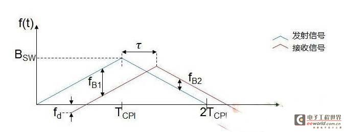
The LFMCW waveform is as follows. The distance and speed of a single target are obtained through a set of beat frequencies at the rising and falling edges. However, in the case of multiple targets, there are N2 combinations of beat frequencies generated by N actual targets, which ultimately result in N2-N false targets.

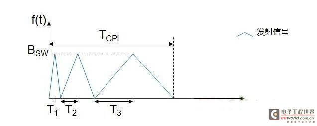
There are many types of CVS waveforms, as shown in the figure below. The transmitter transmits three signals with the same FM bandwidth and different FM slopes within TCPI, with durations of 2T1, 2T2 and 2T3 respectively.

When processing the echo signal, the same algorithm as LFMCW is used for the three segments of the signal, and three groups of N2 distance-speed values are finally obtained. For the real target, the distance-speed values obtained in the three operations should be the same. For the false target, the distance-speed value will change with the change of the frequency modulation period. Therefore, as long as the N overlapping distance-speed values are found from the three groups of results, the distance and speed of the real target can be obtained. Compared with LFMCW, this waveform can remove false targets, and the amount of data processing calculations is also increased, which puts higher requirements on hardware capabilities.
2. Multi-Frequency Shift Keying Radar (MFSK)
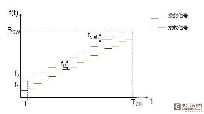
This is a waveform designed specifically for automotive applications. It is generated by combining a linear frequency modulated continuous wave (LFMCW) and a frequency shift keyed wave (FSK). As shown in the figure below, the transmit waveform contains two linearly modulated, interleaved step-up signals. Sequence 1 is used as a reference signal, and the transmit frequency difference between sequence 2 and sequence 1 is fshift. The received signal is down-mixed to obtain a baseband signal and is sampled at each frequency step.

Baseband signal sequences 1 and 2 will undergo the same FFT and CFAR processing. In the case of a single detection target, a target with a specific speed and distance will be detected at the same frequency of the FFT processing results of the two sequences. Similar to LFMCW, the difference frequency fB contains both distance and speed information, but the phase difference of the two signals at the same frequency also contains distance and speed information. Therefore, fB and (symbol 1) need to be used simultaneously in a measurement cycle to resolve distance and speed.
In this case, false targets can be completely avoided. Compared with LFMCW, since MFSK introduces phase difference information when calculating distance and speed, its accuracy will decrease when the system design can only achieve a lower signal-to-noise ratio.
3. Fast ramp sequence radar
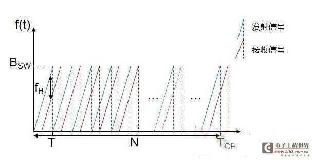
The transmitter continuously transmits N sawtooth waves with large slopes within the time TCPI, and each sawtooth wave lasts for T. Because each sawtooth wave has a large slope and a short duration, the beat frequency fB is mainly determined by the change in the transmission time of the radar signal, that is, fτ. In this case, the Doppler frequency shift fd can be approximately ignored, that is, fB=fd+fτ≈fτ.

In signal processing, the beat frequency fB detected after performing FFT (one-dimensional FFT) on the sampling point sequence in each sawtooth wave can be directly used to estimate the distance. For the measurement of relative speed, all sawtooth waves emitted in the entire TCPI need to participate together to reflect the envelope change of the echo signal. Performing another FFT (two-dimensional FFT) on the one-dimensional FFT results of all sawtooth waves in another dimension can calculate the Doppler frequency shift fd and then the relative speed. The relative speed can further correct the calculation result of the one-dimensional FFT for the distance.
This waveform and subsequent processing algorithm can solve the distance and relative speed more directly and accurately. At the same time, the two-dimensional FFT can further improve the signal-to-noise ratio of the signal, thus laying a good foundation for the subsequent detection algorithm. At the same time, the short duration of a single sawtooth wave requires a faster transmission modulation control circuit, a higher baseband sampling rate, and the two-dimensional FFT algorithm also requires stronger processor computing power, which puts higher requirements on the hardware.
From the above three commonly used frequency modulation systems, we can see that different systems have their own advantages and disadvantages in terms of ranging and speed measurement performance, and have different requirements for hardware capabilities. Radar system designers need to carefully weigh the selected system and the corresponding software and hardware architecture at the beginning in order to achieve the expected system performance in the later stage.
The radar modulation phase-locked loop chip ADF4158/4159 launched by ADI can support most of the mainstream frequency modulation systems of vehicle-mounted radar, including the above-mentioned CVS, MFSK, FRCS, as well as conventional LFMCW, FSK, CW, Parabolic, etc. Its bandwidth, period, frequency modulation steps, step frequency, frequency modulation slope and waveform, FSK, delay and other parameters can be easily configured. Combined with the transceiver MMIC chips ADF5901 and ADF5904, designers can design and verify multiple frequency modulation systems and baseband algorithms on the same hardware architecture. More importantly, compared with the solution of using a processor or DAC to control frequency modulation, the solution based on ADF415x can achieve more complex waveforms, simpler control, faster frequency sweep (as fast as a ramp sequence of tens of uS), and more accurate frequency control to meet the requirements of high-precision signal processing at the back end.
ADF5901 and ADF5904 are MMIC chips launched by ADI for 24GHz vehicle-mounted radars. Their functions and indicators are designed according to vehicle-mounted 24GHz radars. ADF5904 has achieved the industry's best signal detection sensitivity. Some manufacturers have achieved a vehicle-mounted detection distance of more than 300 meters at rated transmission power based on it, making ACC adaptive cruise control or FCW+ACC dual-mode radar based on 24GHz possible for the first time.
Compared with distance and speed, the target azimuth angle is mainly calculated based on the phase difference caused by the time difference of the echo signal reaching different antennas. The more receiving antennas there are, the higher the resolution of the angle measurement is, but the increase in the number of receiving antennas increases the circuit board area. With the application of MIMO technology in automotive radar, the relationship between different transmitting antennas can be used to simulate more receiving antenna channels without significantly increasing the circuit board area. This requires that the MMIC chip must have the ability to transmit and receive multiple times. ADF5901 and ADF5904 support 2 transmit and 4 receive channels. The two transmit channels can be connected to two transmit antennas with different FOVs to achieve dual-mode coverage, or they can be connected to two identical transmit antennas to achieve MIMO functions, which is equivalent to the effect of 1 transmit and 8 receive. With the development of digital spatial filtering technology, digital beamforming (DBF) technology can further improve the accuracy of angle measurement. Similarly, DBF requires more data calculations and stronger hardware capabilities to support it.
The BF70x series DSP launched by ADI for this application has a maximum frequency of 400MHz and 1MB of internal SRAM, and supports external DDR2 memory. For FFT operations, the two enhanced multipliers of BF70x can each complete a 32-bit or two 16-bit multiplication and addition calculations in a single cycle. A large number of optimized mathematical operation functions and butterfly operators and other data can be solidified in the built-in ROM before leaving the factory, saving a lot of valuable internal instructions and data space. These features can help users implement more complex radar algorithms in a shorter operation time.
ADF5901-ADF5904-ADF415x-BF70x constitutes a 24GHz automotive radar solution with excellent hardware performance and software scalability, which meets the requirements of the mainstream frequency modulation system and baseband algorithm discussed above for radar hardware architecture and data processing capabilities.
Previous article:Design of driving recorder based on CAN bus
Next article:Analysis of the automotive electronic driving recorder circuit
- Popular Resources
- Popular amplifiers
 Professor at Beihang University, dedicated to promoting microcontrollers and embedded systems for over 20 years.
- LED chemical incompatibility test to see which chemicals LEDs can be used with
- Application of ARM9 hardware coprocessor on WinCE embedded motherboard
- What are the key points for selecting rotor flowmeter?
- LM317 high power charger circuit
- A brief analysis of Embest's application and development of embedded medical devices
- Single-phase RC protection circuit
- stm32 PVD programmable voltage monitor
- Introduction and measurement of edge trigger and level trigger of 51 single chip microcomputer
- Improved design of Linux system software shell protection technology
- What to do if the ABB robot protection device stops
- Allegro MicroSystems Introduces Advanced Magnetic and Inductive Position Sensing Solutions at Electronica 2024
- Car key in the left hand, liveness detection radar in the right hand, UWB is imperative for cars!
- After a decade of rapid development, domestic CIS has entered the market
- Aegis Dagger Battery + Thor EM-i Super Hybrid, Geely New Energy has thrown out two "king bombs"
- A brief discussion on functional safety - fault, error, and failure
- In the smart car 2.0 cycle, these core industry chains are facing major opportunities!
- The United States and Japan are developing new batteries. CATL faces challenges? How should China's new energy battery industry respond?
- Murata launches high-precision 6-axis inertial sensor for automobiles
- Ford patents pre-charge alarm to help save costs and respond to emergencies
- New real-time microcontroller system from Texas Instruments enables smarter processing in automotive and industrial applications
- Prize-winning live broadcast: How to reduce design errors? Registration for Mentor PCB online seminar opens on July 7!
- Share CC2541 Bluetooth clock settings
- Analysis of the structure and working principle of single chip microcomputer serial communication
- [Synopsys IP Resources] How to fully support electric vehicle virtualization verification from system to software
- Basic functions of linear charger
- "Playing with the board" + servo experiment based on STM32F030Disco
- A place that I don't understand
- [Hua Diao Experience] 12 Building the Arduino development environment for ESP32C3
- 08. Anlu SparkRoad Domestic FPGA Evaluation [Learning] VGA Display
- Chuanglong Technology Allwinner A40i Development Board Review 3 Installation of Linux SDK and Lessons Learned

 OPA344UA/2K5


 京公网安备 11010802033920号