The extensive use of traditional transformer rectifiers and nonlinear loads results in a high current harmonic content in the power grid, which has a great impact on the aircraft power supply system and power supply quality. Eliminating power grid harmonic pollution and improving the power factor of the rectifier are hot topics in the field of power electronics. Space vector PWM (SVPWM) control has the characteristics of high DC side voltage utilization, fast dynamic response and easy digital implementation. This paper uses space vector technology to study the three-phase voltage type rectifier, so that the grid side voltage and current are in phase, thereby achieving high power factor rectification.
1 Space vector control technology
SVPWM control technology controls the space voltage vector V to rotate in a circle according to the set parameters by controlling the combination of different switching states. Any given space voltage vector V can be synthesized by these 8 space vectors, as shown in Figure 1. The voltage vector V of any sector area can be obtained by the different time combinations of the two adjacent non-zero vectors and the zero vector that make up this area. The action time of these vectors can be applied once or multiple times within a sampling period. In other words, SVPWM controls the action time of each basic space voltage vector to eventually form a PWM pulse wave of equal amplitude and unequal width, so that the voltage space vector rotates close to a circular trajectory. The higher the switching frequency of the power switch tube of the main circuit, the closer it is to a circular rotating magnetic field.

In order to reduce the number of switching times and reduce switching losses, for a given space voltage vector of a three-phase VSR,
, using the synthesis method shown in Figure 2. The corresponding switching function in sector I is shown in Figure 3. The zero vectors are evenly distributed in the vector
At the starting and ending points, except for the zero vector,
It is composed of V1, V2, and V4, and the midpoint cuts out two triangles. In one switching cycle, the VSR upper bridge arm power switch is switched on and off four times. Due to the symmetry of the switching function waveform, the harmonics are mainly concentrated on the integer multiples of the switching frequency.

2 Direct current control strategy
The current control strategy of three-phase VSR is mainly divided into direct current control and indirect current control. Direct current control adopts closed-loop control of grid-side current, which improves the dynamic and static performance of grid-side current and enhances the robustness of current control system. In the direct control strategy, PWM current control with fixed switching frequency has been well applied because of its simple algorithm and convenient implementation. In the three-phase stationary coordinate system, the steady-state current command of the inner loop of the PWM current control current with fixed switching frequency is a sinusoidal wave signal. The amplitude signal of the current command comes from the output of the DC voltage regulator, and the frequency and phase signals come from the power grid; the PI current regulator cannot realize zero-static-error control of current, and it is difficult to achieve independent control of active current and reactive current. The current command in the two-phase synchronous rotating coordinate system (d, q) is a DC time-invariant signal, and its PI current regulator realizes zero-static-error control of current, which is also beneficial to control the active current separately.
and reactive current
Independent control.
3 Three-phase VSR digital control system
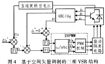
The structure of the three-phase VSR digital control system is shown in Figure 4. The control system uses a voltage outer loop and two current inner loops to form a dual-loop control structure. The voltage loop controls the DC side voltage of the three-phase VSR. The output DC side voltage Vdc is compared with the given reference voltage.
The difference is adjusted by PI to generate a current reference signal
, which serves the purpose of tracking and controlling the output DC voltage; the current loop is used to control the current according to the current command output by the voltage loop regulator, and the current signal output by the voltage outer loop
The input current is controlled and the SVPWM algorithm is used to generate a switching signal to control the rectifier to achieve unity power factor.

The three-phase PWM rectifier uses the idea of motor vector control to adjust the voltage by controlling the current. The sampled three-phase current is transformed by CLARK and PARK coordinates to obtain the id and iq components in the two-phase rotating coordinate system. The voltage error signal is adjusted by PI as the active current command value, and the reactive current
The command value can be directly set to zero, the command voltage of the three-phase VSR is obtained by decoupling, and the control signal of the three-phase rectifier is obtained by the SVPWM algorithm.
3.1 AC side voltage conditioning circuit
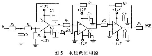
The given input voltage on the system grid side is three-phase AC 115 V. When sampling the voltage, the voltage is stepped down through a transformer, and then the voltage signal is conditioned so that the voltage signal value is between 0 and 3 V as required by the data acquisition end of TMS320F281 2. The voltage conditioning circuit is shown in Figure 5.

3.2 DC voltage conditioning circuit
The DC side output voltage is about 350 V. In order to realize the data acquisition of the DC side voltage, an operational amplifier is used to form a dual-input amplifier circuit. By selecting reasonable parameter values, the DC side output voltage is converted to the range of 0~3 V and then sent to the AD interface of the DSP.
3.3 TMS320F2812 program initialization process
Through the detailed analysis of the control algorithm of space vector pulse width modulation technology and the modeling and simulation of three-phase VSR, it is found that the control algorithm of SVPWM has the characteristics of being easy to realize digitally. The low-power, low-cost and fairly integrated fixed-point TMS320F2812, which has been developed relatively maturely, is selected as the core controller. This device is a new generation of low-price, high-performance 32-bit fixed-point digital signal processor DSP launched by Tl Company. The digital signal processor is an important part of the three-phase high power factor rectifier. The software part implemented by TMS320F2812 mainly includes the main program and interrupt subroutine. The main program mainly completes the initialization of the system, including system clock setting, initialization register value, opening global interrupt and opening event manager interrupt to enter the working state. Its program flow is shown in Figure 6.

4 Test results
According to the mathematical model and related principles of three-phase VSR, an experimental circuit was built in the laboratory and tested. In the test, the power supply is 115 V/400 Hz three-phase AC power supply. When the load is 217Ω, the grid-side A-phase input voltage and A-phase input current waveforms are measured as shown in Figure 7. It can be seen from Figure 7 that the input voltage and input current are in phase, thus achieving high power factor rectification.

5 Conclusion
In order to meet the requirements of aviation rectifiers for low harmonics, high power factor, fast response, stable DC output, etc., a new SVPWM control strategy that is easy to digitally implement is proposed using input voltage space vector orientation. It can be seen from the test results that the grid-side current of the rectifier designed with space vector control technology follows the grid-side voltage well, achieving high power factor rectification and meeting the design requirements.
Previous article:Metal film resistor temperature detection circuit diagram
Next article:Research on virtual chemical scene optimization technology based on EON
Recommended ReadingLatest update time:2024-11-16 19:54


- Popular Resources
- Popular amplifiers
-
 Modern arc welding power supply and its control
 -
 Intelligent Control Technology of Permanent Magnet Synchronous Motor (Written by Wang Jun)
 -
 Simulation and implementation of improved SVPWM algorithm based on FPGA_Yang Yunyi
 -
 A review of learning-based camera and lidar simulation methods for autonomous driving systems
- Molex leverages SAP solutions to drive smart supply chain collaboration
- Pickering Launches New Future-Proof PXIe Single-Slot Controller for High-Performance Test and Measurement Applications
- CGD and Qorvo to jointly revolutionize motor control solutions
- Advanced gameplay, Harting takes your PCB board connection to a new level!
- Nidec Intelligent Motion is the first to launch an electric clutch ECU for two-wheeled vehicles
- Bosch and Tsinghua University renew cooperation agreement on artificial intelligence research to jointly promote the development of artificial intelligence in the industrial field
- GigaDevice unveils new MCU products, deeply unlocking industrial application scenarios with diversified products and solutions
- Advantech: Investing in Edge AI Innovation to Drive an Intelligent Future
- CGD and QORVO will revolutionize motor control solutions
- Innolux's intelligent steer-by-wire solution makes cars smarter and safer
- 8051 MCU - Parity Check
- How to efficiently balance the sensitivity of tactile sensing interfaces
- What should I do if the servo motor shakes? What causes the servo motor to shake quickly?
- 【Brushless Motor】Analysis of three-phase BLDC motor and sharing of two popular development boards
- Midea Industrial Technology's subsidiaries Clou Electronics and Hekang New Energy jointly appeared at the Munich Battery Energy Storage Exhibition and Solar Energy Exhibition
- Guoxin Sichen | Application of ferroelectric memory PB85RS2MC in power battery management, with a capacity of 2M
- Analysis of common faults of frequency converter
- In a head-on competition with Qualcomm, what kind of cockpit products has Intel come up with?
- Dalian Rongke's all-vanadium liquid flow battery energy storage equipment industrialization project has entered the sprint stage before production
- Allegro MicroSystems Introduces Advanced Magnetic and Inductive Position Sensing Solutions at Electronica 2024
- Car key in the left hand, liveness detection radar in the right hand, UWB is imperative for cars!
- After a decade of rapid development, domestic CIS has entered the market
- Aegis Dagger Battery + Thor EM-i Super Hybrid, Geely New Energy has thrown out two "king bombs"
- A brief discussion on functional safety - fault, error, and failure
- In the smart car 2.0 cycle, these core industry chains are facing major opportunities!
- The United States and Japan are developing new batteries. CATL faces challenges? How should China's new energy battery industry respond?
- Murata launches high-precision 6-axis inertial sensor for automobiles
- Ford patents pre-charge alarm to help save costs and respond to emergencies
- New real-time microcontroller system from Texas Instruments enables smarter processing in automotive and industrial applications
- PIC microcontroller reads battery information and outputs it via serial port
- MSP430G2553 SPI UART
- Qorvo's 2020 review and expectations for 2021
- TIOBE June Programming Language Ranking: Python is expected to surpass C to become the first
- A strange problem when compiling a KEIL project
- LNA Design of ATF54143
- Micropython does not support GBK encoding
- The onboard microstrip antenna can completely replace the external IPEX antenna
- JTAG cannot recognize DSP processing
- What is a polarized relay?

 Modern arc welding power supply and its control


 京公网安备 11010802033920号