Overview
The so-called "noise floor" usually refers to the "baseline noise floor" of the oscilloscope, which is the vertical noise caused by the analog front end and digital conversion process of the oscilloscope. The noise floor appears on the oscilloscope screen as the noise waveform generated when the oscilloscope is set to the most sensitive vertical position (minimum vertical position). The noise floor of the oscilloscope is related to the components used in the instrument, hardware design, signal processing, and other aspects. In addition, when testing and comparing the noise floor of the instrument, there are many factors that affect the noise test results, such as: bandwidth, sampling rate, channel vertical resolution, horizontal time base position, and channel coupling mode. Generally, the noise floor value measured under DC coupling and full bandwidth is more accurate.
How to measure the noise floor
Here is how to measure the oscilloscope noise floor:
(1) Ensure that the oscilloscope is in normal operating condition;
(2) Do not connect the probe to the oscilloscope or short-circuit the BNC terminal of the oscilloscope probe with the ground terminal;
(3) Set appropriate horizontal and vertical time base gears (usually very sensitive gears, such as 2mv/div, 1us/div, etc.);
(4) Short press the [Trigger] knob to adjust the trigger level so that the background noise waveform is displayed stably;
(5) Since the oscilloscope screen displays the peak deviation of the noise, the most intuitive measurement parameter for the background noise is the peak-to-peak measurement. Press [Measure] and select "Peak-to-peak" measurement.
10.3.3 Noise Floor of ZDS2022 Oscilloscope
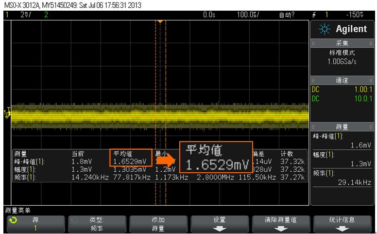
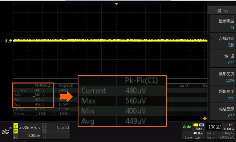
To more clearly illustrate the noise floor of the ZDS2022 oscilloscope, the following is a comparison with Tektronix and Agilent oscilloscopes.
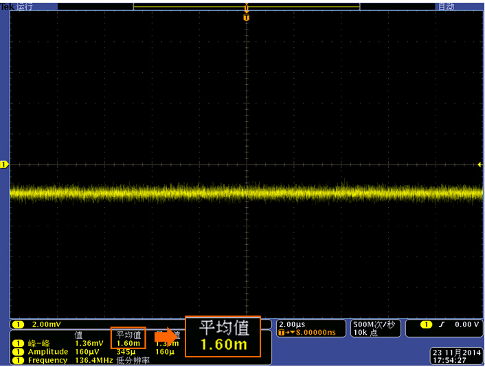
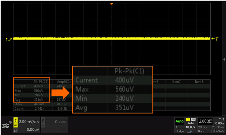
As shown in Figure 10.1 and Figure 10.2, when the horizontal time base is 2us/div and the vertical time base is 2ms/div, the peak-to-peak value average measured by the MSO4054 oscilloscope (sampling rate is 500MSa/S) is 1.60mV, while the peak-to-peak value average measured by the ZDS2022 oscilloscope (sampling rate is 1GSa/S) is 351uV. Theoretically, the higher the sampling rate, the clearer the waveform details, and the greater the noise floor should be, but from the measurement results, it can be seen that the noise floor of the ZDS2022 oscilloscope is significantly better than that of the Tektronix MSO4054 oscilloscope.

Figure 10 1Tek's MSO4054 noise floor

Figure 10 2ZDS2022 oscilloscope noise floor 1

Figure 10 3Agilent MSO-X3012A noise floor

Figure 10 4ZDS2022 oscilloscope noise floor 2
Previous article:How high is the measurement accuracy of the ZDS2022 oscilloscope?
Next article:Why does the waveform respond slowly when adjusting the time base?
- Popular Resources
- Popular amplifiers
- Seizing the Opportunities in the Chinese Application Market: NI's Challenges and Answers
- Tektronix Launches Breakthrough Power Measurement Tools to Accelerate Innovation as Global Electrification Accelerates
- Not all oscilloscopes are created equal: Why ADCs and low noise floor matter
- Enable TekHSI high-speed interface function to accelerate the remote transmission of waveform data
- How to measure the quality of soft start thyristor
- How to use a multimeter to judge whether a soft starter is good or bad
- What are the advantages and disadvantages of non-contact temperature sensors?
- In what situations are non-contact temperature sensors widely used?
- How non-contact temperature sensors measure internal temperature
- LED chemical incompatibility test to see which chemicals LEDs can be used with
- Application of ARM9 hardware coprocessor on WinCE embedded motherboard
- What are the key points for selecting rotor flowmeter?
- LM317 high power charger circuit
- A brief analysis of Embest's application and development of embedded medical devices
- Single-phase RC protection circuit
- stm32 PVD programmable voltage monitor
- Introduction and measurement of edge trigger and level trigger of 51 single chip microcomputer
- Improved design of Linux system software shell protection technology
- What to do if the ABB robot protection device stops
- CGD and Qorvo to jointly revolutionize motor control solutions
- CGD and Qorvo to jointly revolutionize motor control solutions
- Keysight Technologies FieldFox handheld analyzer with VDI spread spectrum module to achieve millimeter wave analysis function
- Infineon's PASCO2V15 XENSIV PAS CO2 5V Sensor Now Available at Mouser for Accurate CO2 Level Measurement
- Advanced gameplay, Harting takes your PCB board connection to a new level!
- Advanced gameplay, Harting takes your PCB board connection to a new level!
- A new chapter in Great Wall Motors R&D: solid-state battery technology leads the future
- Naxin Micro provides full-scenario GaN driver IC solutions
- Interpreting Huawei’s new solid-state battery patent, will it challenge CATL in 2030?
- Are pure electric/plug-in hybrid vehicles going crazy? A Chinese company has launched the world's first -40℃ dischargeable hybrid battery that is not afraid of cold
- RISC-V MCU Development (Part 14): Help and Feedback
- Don’t get lost in power supply design by reading “Selected Basic Knowledge of Power Supply Design” which can be downloaded for free!
- Mir MYC-YT507 development board review: performance test one coremark running score
- PCB design, which tool software is the best?
- IAR settings let the code run from reset instead of main
- The 19th year holiday schedule is here.
- What basics are needed to learn programming?
- [National Technology N32G457 Review] Implementation of Environmental Status Detection Device
- [BearPi-HM Nano, play Hongmeng "Touch and Go"] Part 2: Setting up the environment is so simple
- Failed to set default vias in Altium Designer?

 MIC860BC5


 京公网安备 11010802033920号